
Page 55 - Petroleum Production Engineering, A Computer-Assisted Approach
P. 55
Guo, Boyun / Petroleum Production Engineering, A Computer-Assisted Approach 0750682701_chap04 Final Proof page 46 22.12.2006 6:07pm
4/46 PETROLEUM PRODUCTION ENGINEERING FUNDAMENTALS
4.1 Introduction g ¼ gravitational acceleration, 32:17 ft=s 2
g c ¼ unit conversion factor, 32:17 lb m -ft=lb f -s 2
Chapter 3 described reservoir deliverability. However, the 3
achievable oil production rate from a well is determined by r ¼ fluid density lb m =ft
wellhead pressure and the flow performance of production z ¼ elevation increase, ft
string, that is, tubing, casing, or both. The flow perform- u ¼ fluid velocity, ft/s
ance of production string depends on geometries of the f F ¼ Fanning friction factor
production string and properties of fluids being produced. L ¼ tubing length, ft
The fluids in oil wells include oil, water, gas, and sand. D ¼ tubing inner diameter, ft
Wellbore performance analysis involves establishing a re- The first, second, and third term in the right-hand side
lationship between tubular size, wellhead and bottom-hole of the equation represent pressure drops due to changes in
pressure, fluid properties, and fluid production rate. elevation, kinetic energy, and friction, respectively.
Understanding wellbore flow performance is vitally im- The Fanning friction factor ( f F ) can be evaluated based
portant to production engineers for designing oil well on Reynolds number and relative roughness. Reynolds num-
equipment and optimizing well production conditions. ber is defined as the ratio of inertial force to viscous force.
Oil can be produced through tubing, casing, or both in The Reynolds number is expressed in consistent units as
an oil well depending on which flow path has better per-
formance. Producing oil through tubing is a better option Dur
in most cases to take the advantage of gas-lift effect. The N Re ¼ (4:2)
traditional term tubing performance relationship (TPR) is m
used in this book (other terms such as vertical lift perform-
ance have been used in the literature). However, the math- or in U.S. field units as
ematical models are also valid for casing flow and casing-
tubing annular flow as long as hydraulic diameter is used. 1:48qr
This chapter focuses on determination of TPR and pres- N Re ¼ dm (4:3)
sure traverse along the well string. Both single-phase and
multiphase fluids are considered. Calculation examples are
where
illustrated with hand calculations and computer spread-
sheets that are provided with this book. N Re ¼ Reynolds number
q ¼ fluid flow rate, bbl/day
r ¼ fluid density lb m =ft 3
4.2 Single-Phase Liquid Flow
d ¼ tubing inner diameter, in.
Single-phase liquid flow exists in an oil well only when the m ¼ fluid viscosity, cp
wellhead pressure is above the bubble-point pressure of the
oil, which is usually not a reality. However, it is convenient For laminar flow where N Re < 2,000, the Fanning
to start from single-phase liquid for establishing the con- friction factor is inversely proportional to the Reynolds
cept of fluid flow in oil wells where multiphase flow usually number, or
dominates.
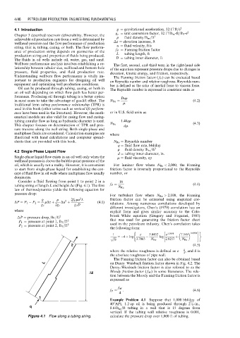
Consider a fluid flowing from point 1 to point 2 in a 16
tubing string of length L and height z (Fig. 4.1). The first f F ¼ (4:4)
N Re
law of thermodynamics yields the following equation for
pressure drop:
For turbulent flow where N Re > 2,100, the Fanning
2
g r 2f F ru L friction factor can be estimated using empirical cor-
2
DP ¼ P 1 P 2 ¼ rDz þ Du þ (4:1) relations. Among numerous correlations developed by
g c 2g c g c D
different investigators, Chen’s (1979) correlation has an
where explicit form and gives similar accuracy to the Cole-
P ¼ pressure drop, lb f =ft 2 brook–White equation (Gregory and Fogarasi, 1985)
P 1 ¼ pressure at point 1, lb f =ft 2 that was used for generating the friction factor chart
P 2 ¼ pressure at point 2, lb f =ft 2 used in the petroleum industry. Chen’s correlation takes
the following form:
( " #)
1 « 5:0452 « 1:1098 7:149 0:8981
p ffiffiffiffiffi ¼ 4 log log þ
f F 3:7065 N Re 2:8257 N Re
2 (4:5)
d
where the relative roughness is defined as « ¼ , and d is
d
the absolute roughness of pipe wall.
The Fanning friction factor can also be obtained based
L on Darcy–Wiesbach friction factor shown in Fig. 4.2. The
Darcy–Wiesbach friction factor is also referred to as the
∆z Moody friction factor ( f M ) in some literatures. The rela-
tion between the Moody and the Fanning friction factor is
expressed as
f M
f F ¼ : (4:6)
4
1
Example Problem 4.1 Suppose that 1,000 bbl/day of
7
408API, 1.2 cp oil is being produced through 2 ⁄ 8 -in.,
q
8:6-lb m =ft tubing in a well that is 15 degrees from
vertical. If the tubing wall relative roughness is 0.001,
Figure 4.1 Flow along a tubing string. calculate the pressure drop over 1,000 ft of tubing.