
Page 58 - Petroleum Production Engineering, A Computer-Assisted Approach
P. 58
Guo, Boyun / Petroleum Production Engineering, A Computer-Assisted Approach 0750682701_chap04 Final Proof page 49 22.12.2006 6:07pm
WELLBORE PERFORMANCE 4/49
Flow Direction
O P O R
10
Annular
Mist
(Water
dispersed)
Superficial Water Velocity, V SL , ft./sec. 1.0
N
M
H
I
L
K
J
Froth
dispersed)
Slug 4
Bubble
(Air dispersed) (Air dispersed) (Both phases
A B C D E F G
0.1
0.1 1.0 10 100
, ft./sec.
Superficial Gas Velocity, V SG
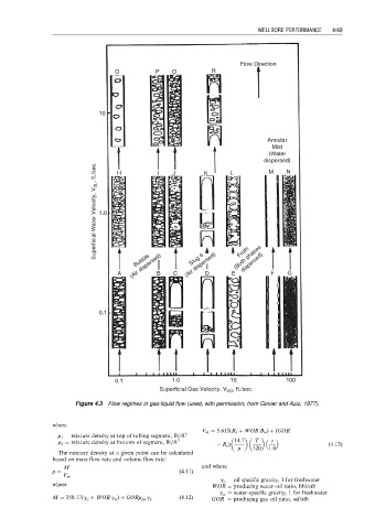
Figure 4.3 Flow regimes in gas-liquid flow (used, with permission, from Govier and Aziz, 1977).
where
V m ¼ 5:615(B o þ WOR B w ) þ (GOR
r 1 ¼ mixture density at top of tubing segment, lb=ft 3
r 2 ¼ mixture density at bottom of segment, lb=ft 3 R s ) 14:7 T z (4:13)
p 520 1:0
The mixture density at a given point can be calculated
based on mass flow rate and volume flow rate:
M and where
r ¼ (4:11)
V m
g o ¼ oil specific gravity, 1 for freshwater
where WOR ¼ producing water–oil ratio, bbl/stb
g w ¼ water-specific gravity, 1 for freshwater
(4:12)
M ¼ 350:17(g o þ WOR g w ) þ GORr air g g GOR ¼ producing gas–oil ratio, scf/stb