
Page 72 - Petroleum Production Engineering, A Computer-Assisted Approach
P. 72
Guo, Boyun / Petroleum Production Engineering, A Computer-Assisted Approach 0750682701_chap05 Final Proof page 63 21.12.2006 2:02pm
CHOKE PERFORMANCE 5/63
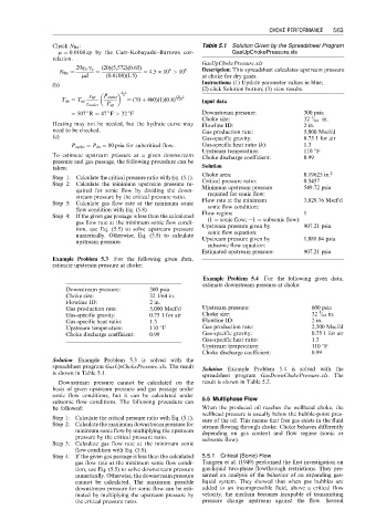
Check N Re : Table 5.1 Solution Given by the Spreadsheet Program
m ¼ 0:0108 cp by the Carr–Kobayashi–Burrows cor- GasUpChokePressure.xls
relation.
GasUpChokePressure.xls
20q sc g g (20)(5,572)(0:65) Description: This spreadsheet calculates upstream pressure
6
N Re ¼ ¼ ¼ 4:5 10 > 10 6
md (0:0108)(1:5) at choke for dry gases.
Instructions: (1) Update parameter values in blue;
(b)
k 1 (2) click Solution button; (3) view results.
k
z up P outlet 1:25 1
T dn ¼ T up ¼ (70 þ 460)(1)(0:8) 1:25 Input data
z outlet P up
¼ 507 R ¼ 47 F > 32 F Downstream pressure: 300 psia
1
Choke size: 32 ⁄ 64 in.
Heating may not be needed, but the hydrate curve may Flowline ID: 2 in.
need to be checked. Gas production rate: 5,000 Mscf/d
(c) Gas-specific gravity: 0.75 1 for air
P outlet ¼ P dn ¼ 80 psia for subcritical flow: Gas-specific heat ratio (k): 1.3
Upstream temperature: 110 8F
To estimate upstream pressure at a given downstream Choke discharge coefficient: 0.99
pressure and gas passage, the following procedure can be
taken: Solution
Choke area: 0.19625 in: 2
Step 1: Calculate the critical pressure ratio with Eq. (5.1).
Step 2: Calculate the minimum upstream pressure re- Critical pressure ratio: 0.5457
quired for sonic flow by dividing the down- Minimum upstream pressure 549.72 psia
stream pressure by the critical pressure ratio. required for sonic flow:
Step 3: Calculate gas flow rate at the minimum sonic Flow rate at the minimum 3,029.76 Mscf/d
flow condition with Eq. (5.8). sonic flow condition:
Step 4: If the given gas passage is less than the calculated Flow regime 1
gas flow rate at the minimum sonic flow condi- (1 ¼ sonic flow; 1 ¼ subsonic flow):
tion, use Eq. (5.5) to solve upstream pressure Upstream pressure given by 907.21 psia
numerically. Otherwise, Eq. (5.8) to calculate sonic flow equation:
upstream pressure. Upstream pressure given by 1,088.04 psia
subsonic flow equation:
Estimated upstream pressure: 907.21 psia
Example Problem 5.3 For the following given data,
estimate upstream pressure at choke:
Example Problem 5.4 For the following given data,
estimate downstream pressure at choke:
Downstream pressure: 300 psia
Choke size: 32 1/64 in.
Flowline ID: 2 in.
Gas production rate: 5,000 Mscf/d Upstream pressure: 600 psia
1
Gas-specific gravity: 0.75 1 for air Choke size: 32 ⁄ 64 in.
Gas-specific heat ratio: 1.3 Flowline ID: 2 in.
Upstream temperature: 110 8F Gas production rate: 2,500 Mscf/d
Choke discharge coefficient: 0.99 Gas-specific gravity: 0.75 1 for air
Gas-specific heat ratio: 1.3
Upstream temperature: 110 8F
Choke discharge coefficient: 0.99
Solution Example Problem 5.3 is solved with the
spreadsheet program GasUpChokePressure.xls. The result Solution Example Problem 5.4 is solved with the
is shown in Table 5.1.
spreadsheet program GasDownChokePressure.xls. The
Downstream pressure cannot be calculated on the result is shown in Table 5.2.
basis of given upstream pressure and gas passage under
sonic flow conditions, but it can be calculated under
subsonic flow conditions. The following procedure can 5.5 Multiphase Flow
be followed: When the produced oil reaches the wellhead choke, the
wellhead pressure is usually below the bubble-point pres-
Step 1: Calculate the critical pressure ratio with Eq. (5.1). sure of the oil. This means that free gas exists in the fluid
Step 2: Calculate the maximum downstream pressure for stream flowing through choke. Choke behaves differently
minimum sonic flow by multiplying the upstream depending on gas content and flow regime (sonic or
pressure by the critical pressure ratio. subsonic flow).
Step 3: Calculate gas flow rate at the minimum sonic
flow condition with Eq. (5.8).
Step 4: If the given gas passage is less than the calculated 5.5.1 Critical (Sonic) Flow
gas flow rate at the minimum sonic flow condi- Tangren et al. (1949) performed the first investigation on
tion, use Eq. (5.5) to solve downstream pressure gas-liquid two-phase flowthrough restrictions. They pre-
numerically. Otherwise, the downstream pressure sented an analysis of the behavior of an expanding gas-
cannot be calculated. The maximum possible liquid system. They showed that when gas bubbles are
downstream pressure for sonic flow can be esti- added to an incompressible fluid, above a critical flow
mated by multiplying the upstream pressure by velocity, the medium becomes incapable of transmitting
the critical pressure ratio. pressure change upstream against the flow. Several