
Page 69 - Petroleum Production Engineering, A Computer-Assisted Approach
P. 69
Guo, Boyun / Petroleum Production Engineering, A Computer-Assisted Approach 0750682701_chap05 Final Proof page 60 21.12.2006 2:02pm
5/60 PETROLEUM PRODUCTION ENGINEERING FUNDAMENTALS
5.1 Introduction
Wellhead chokes are used to limit production rates for
regulations, protect surface equipment from slugging,
avoid sand problems due to high drawdown, and control q d 1 d 2
flow rate to avoid water or gas coning. Two types of well- p 1 p 2
head chokes are used. They are (1) positive (fixed) chokes
and (2) adjustable chokes.
Placing a choke at the wellhead means fixing the well-
head pressure and, thus, the flowing bottom-hole pressure
and production rate. For a given wellhead pressure, by 0.3
calculating pressure loss in the tubing the flowing bottom-
hole pressure can be determined. If the reservoir pressure
and productivity index is known, the flow rate can then be
determined on the basis of inflow performance relation-
ship (IPR). 0.2
5.2 Sonic and Subsonic Flow
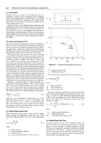
q Critical
Pressure drop across well chokes is usually very significant.
There is no universal equation for predicting pressure drop Sub-
across the chokes for all types of production fluids. Differ- 0.1 critical
ent choke flow models are available from the literature,
and they have to be chosen based on the gas fraction in the
fluid and flow regimes, that is, subsonic or sonic flow.
Both sound wave and pressure wave are mechanical
waves. When the fluid flow velocity in a choke reaches the
traveling velocity of sound in the fluid under the in situ 0
condition, the flow is called ‘‘sonic flow.’’ Under sonic 0 0.2 0.4 0.6 0.8 1 1.2
flow conditions, the pressure wave downstream of the p /p 1
2
choke cannot go upstream through the choke because the
medium (fluid) is traveling in the opposite direction at the Figure 5.1 A typical choke performance curve.
same velocity. Therefore, a pressure discontinuity exists at
the choke, that is, the downstream pressure does not affect
the upstream pressure. Because of the pressure discontinu- P ¼ pressure drop, lb f =ft 2
ity at the choke, any change in the downstream pressure r ¼ fluid density, lb m =ft 3
cannot be detected from the upstream pressure gauge. Of
course, any change in the upstream pressure cannot be If U.S. field units are used, Eq. (5.2) is expressed as
detected from the downstream pressure gauge either. This s ffiffiffiffiffiffi
sonic flow provides a unique choke feature that stabilizes q ¼ 8074C D d 2 Dp , (5:3)
well production rate and separation operation conditions. 2 r
Whether a sonic flow exists at a choke depends on a where
downstream-to-upstream pressure ratio. If this pressure
ratio is less than a critical pressure ratio, sonic (critical) q ¼ flow rate, bbl/d
flow exists. If this pressure ratio is greater than or equal to d 2 ¼ choke diameter, in.
the critical pressure ratio, subsonic (subcritical) flow exists. p ¼ pressure drop, psi
The critical pressure ratio through chokes is expressed as
k The choke discharge coefficient C D can be determined
p outlet 2 k 1 based on Reynolds number and choke/pipe diameter ratio
¼ , (5:1)
p up c k þ 1 (Figs. 5.2 and 5.3). The following correlation has been
found to give reasonable accuracy for Reynolds numbers
where p outlet is the pressure at choke outlet, p up is the between 10 and 10 for nozzle-type chokes (Guo and
4
6
upstream pressure, and k ¼ C p =C v is the specific heat Ghalambor, 2005):
ratio. The value of the k is about 1.28 for natural gas.
Thus, the critical pressure ratio is about 0.55 for natural C D ¼ d 2 0:3167 þ 0:025[ log (N Re ) 4], (5:4)
gas. A similar constant is used for oil flow. A typical choke d 1 þ 0:6
d 2
performance curve is shown in Fig. 5.1. d 1
where
5.3 Single-Phase Liquid Flow
d 1 ¼ upstream pipe diameter, in.
When the pressure drop across a choke is due to kinetic d 2 ¼ choke diameter, in.
energy change, for single-phase liquid flow, the second N Re ¼ Reynolds number based on d 2
term in the right-hand side of Eq. (4.1) can be rearranged
as
s ffiffiffiffiffiffiffiffiffiffiffiffiffi 5.4 Single-Phase Gas Flow
2g c DP
q ¼ C D A , (5:2) Pressure equations for gas flow through a choke are
r
derived based on an isentropic process. This is because
where there is no time for heat to transfer (adiabatic) and the
friction loss is negligible (assuming reversible) at chokes.
3
q ¼ flow rate, ft =s In addition to the concern of pressure drop across the
C D ¼ choke discharge coefficient chokes, temperature drop associated with choke flow is
A ¼ choke area, ft 2 also an important issue for gas wells, because hydrates
g c ¼ unit conversion factor, 32.17 lb m -ft=lb f -s 2 may form that may plug flow lines.