
Page 89 - Petroleum Production Engineering, A Computer-Assisted Approach
P. 89
Guo, Boyun / Computer Assited Petroleum Production Engg 0750682701_chap06 Final Proof page 81 3.1.2007 8:40pm Compositor Name: SJoearun
WELL DELIVERABILITY 6/81
4
2
2
z
6:67 10 (e 1)f Mi q z T 2
S i
S i 2
p 2 ¼ e p þ gi i i , (6:33)
5
H n wf i kf i d cos (45 )
i
where
R n 0:0375pg g R i cos (45 )
H 3 L n S i ¼ 2 z i T : (6:34)
z
The friction factor f Mi can be found in the conventional
L 3 R 3 manner for a given tubing diameter, wall roughness, and
H 2
Reynolds number. However, if one assumes fully turbulent
flow, which is the case for most gas wells, then a simple
R 2 L empirical relation may be used for typical tubing strings
H 1 2 (Katz and Lee, 1990):
R
L 1 1 f Mi ¼ 0:01750 for d i # 4:277 in: (6:35)
d 0:224
i
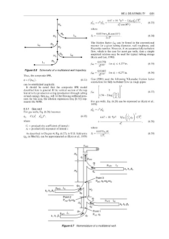
Figure 6.6 Schematic of a multilateral well trajectory. 0:01603
f Mi ¼ 0:164 for d i > 4:277 in: (6:36)
Thus, the composite IPR, d i
q ¼ fp hf n , (6:31) Guo (2001) used the following Nikuradse friction factor
correlation for fully turbulent flow in rough pipes:
can be established implicitly. 2 3 2
It should be noted that the composite IPR model
6
7
described here is general. If the vertical section of the top f Mi ¼ 6 1 7
lateral is the production string (production through tubing 4 2« i 5 (6:37)
will be the flowing wellhead pres- 1:74 2 log
or/and casing), then p hf n
d i
sure. In this case, the relation expression (Eq. [6.31]) rep-
resents the WPR. For gas wells, Eq. (6.28) can be expressed as (Katz et al.,
1959)
6.3.1 Gas well p 2 ¼ e p
S i 2
For gas wells, Eq. (6.26) becomes hf i hf i
! 2
2
2
p
¼ C i ( p p ) , (6:32) P i 2
n i
2
4
z
S i
q g i i wf i 6:67 10 (e 1)f Mi q gi z T i
i
j¼1
where þ , (6:38)
d 5
C i ¼ productivity coefficient of lateral i i
n i ¼ productivity exponent of lateral i. where
0:0375g g H i
As described in Chapter 4, Eq. (6.27), in U.S. field units S i ¼ : (6:39)
(q gi in Mscf/d), can be approximated as (Katz et al., 1959) z z i T i
p wfn
H n
q r p wfn
p wfn L n
R n
k h p n
n
n
H 3 q n
Point 3
P m3' q +q +q 3
1
2
R 3
p wf3 L 3
k h p 3 H 2
3
3
q 3
Point 2
1
P m2' q +q 2 R 2 p wf 2 L 2
H 1
k 2 h 2 p 2
q 2
R 1 Point 1
p wf1 L 1 P q
k 1 h 1 p 1 q 1 m1' 1
Figure 6.7 Nomenclature of a multilateral well.