
Page 410 -
P. 410
~ U :~ :sW~TNE: ( ....... brm backing)
.......... ~ j ~ / ~ sEuMRBREAN~EA(TC~St : ...... backing,
Processed water passes through the membranes on FLOW SPACER
both sides of the porous permeate carrier, SOURCE WATER 4~*
~ SOURCE WATER
Concentrate ~ ~ Adapted from Hydranautics
Water Systems diagram
Pent'eat e ~ .......................................
ed .............. eCtun~ac ..........................
Cutaway view of a spiral membrane module
(a)
PRESSURE VESSEL ANTI-TELESCOPING CONCENTRATE (brine)
SUPPORT SEAL
...................... ////~]] ............. ~'1l]1~ SNAP RING
CONCENTRATE -.,~t.- MODULE MODULE MODULE SOURCE WATER INLET
OUTLET Ill[ ....................... ~ .................. ~ .~. '1~1i.....~ ................. =.,-/=-,.~....=..~
~BRINE SEALS C~RING
CONNECTOR
Cross section of pressure vesset with 3 membrane modules
(b)
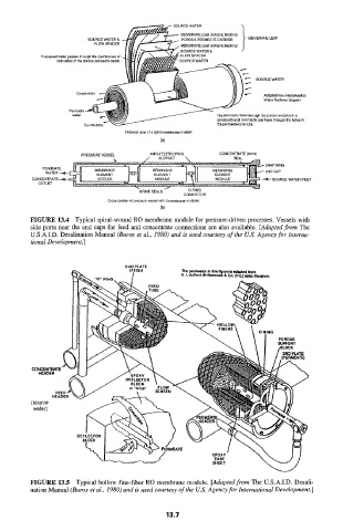
FIGURE 13.4 Typical spiral-wound RO membrane module for pressure-driven processes. Vessels with
side ports near the end caps for feed and concentrate connections are also available. [Adapted from The
U.S.A.I.D. Desalination Manual (Buros et al., 1980) and is used courtesy of the U.S. Agency for Interna-
tional Development.]
CONCENTR
HEADER
N
(source
water)
FIGURE 13.5 Typical hollow fine-fiber RO membrane module. [Adapted from The U.S.A.1.D. Desali-
nation Manual (Buros et al., 1980) and is used courtesy of the U.S. Agency for International Development. ]
13.7