
Page 415 -
P. 415
13.12 CHAPTER THIRTEEN
Split treatment bypass stream (if applicable)
..... ~ I
I
I Membrane unit(s)* I
Concentrale to waste
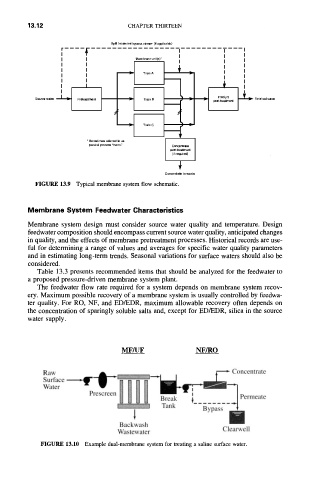
FIGURE 13.9 Typical membrane system flow schematic.
Membrane System Feedwater Characteristics
Membrane system design must consider source water quality and temperature. Design
feedwater composition should encompass current source water quality, anticipated changes
in quality, and the effects of membrane pretreatment processes. Historical records are use-
ful for determining a range of values and averages for specific water quality parameters
and in estimating long-term trends. Seasonal variations for surface waters should also be
considered.
Table 13.3 presents recommended items that should be analyzed for the feedwater to
a proposed pressure-driven membrane system plant.
The feedwater flow rate required for a system depends on membrane system recov-
ery. Maximum possible recovery of a membrane system is usually controlled by feedwa-
ter quality. For RO, NF, and ED/EDR, maximum allowable recovery often depends on
the concentration of sparingly soluble salts and, except for ED/EDR, silica in the source
water supply.
MF/UF NF/RO
Raw A
Surface~ I =
W a t e r - - - - ! i I !
Prescreen
1
Backwash
Clearwell
Wastewater
FIGURE 13.10 Example dual-membrane system for treating a saline surface water.