
Page 411 -
P. 411
13.8 CHAPTER THIRTEEN
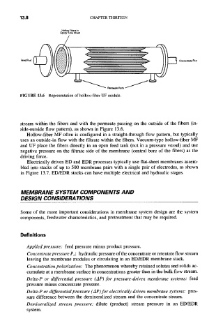
Hollow Fibers in
Epoxy Tube Sheet
Feed Port Concentrate Port
•
Pemleate Ports
FIGURE 13.6 Representation of hollow-fiber UF module.
stream within the fibers and with the permeate passing on the outside of the fibers (in-
side-outside flow pattern), as shown in Figure 13.6.
Hollow-fiber MF often is configured in a straight-through flow pattern, but typically
uses an outside-in flow with the filtrate within the fibers. Vacuum-type hollow-fiber MF
and UF place the fibers directly in an open feed tank (not in a pressure vessel) and use
negative pressure on the filtrate side of the membrane (central bore of the fibers) as the
driving force.
Electrically driven ED and EDR processes typically use fiat-sheet membranes assem-
bled into stacks of up to 500 membrane pairs with a single pair of electrodes, as shown
in Figure 13.7. ED/EDR stacks can have multiple electrical and hydraulic stages.
MEMBRANE SYSTEM COMPONENTS AND
DESIGN CONSIDERATIONS
Some of the more important considerations in membrane system design are the system
components, feedwater characteristics, and pretreatment that may be required.
Definitions
Applied pressure: feed pressure minus product pressure.
Concentrate pressure Pc: hydraulic pressure of the concentrate or retentate flow stream
leaving the membrane modules or circulating in an ED/EDR membrane stack.
Concentration polarization: The phenomenon whereby retained solutes and solids ac-
cumulate at a membrane surface in concentrations greater than in the bulk flow stream.
Delta-P or differential pressure ( Ap) for pressure-driven membrane systems: feed
pressure minus concentrate pressure.
Delta-P or differential pressure (AP) for electrically driven membrane systems: pres-
sure difference between the demineralized stream and the concentrate stream.
Demineralized stream pressure: dilute (product) stream pressure in an ED/EDR
system.