
Page 419 -
P. 419
13.16 CHAPTER THIRTEEN
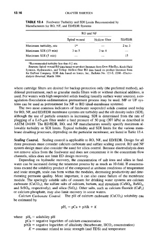
TABLE 13.4 Feedwater Turbidity and SDI Limits Recommended by
Manufacturers for RO, NF, and ED/EDR Systems
RO and NF
Spiral wound Hollow fiber ED/EDR
Maximum turbidity, ntu 1 * -- 2 to 3
Maximum SDI (15 min) 3 to 5 3 to 4 --
Maximum SDI (5 min) -- -- 15
*Recommended turbidity less than 0.2 ntu.
Sources: Spiral-wound RO data based on product literature from Dow-FilmTec, Koch Fluid
Systems, Hydranautics, and TriSep. Hollow-fiber RO data based on product literature from
the DuPont Company. EDR data based on lonics, Inc., Bulletin No. 121-E, EDR--Electro-
dialysis Reversal, March 1984.
where cartridge filters are desired for backup protection only (the preferred method), ad-
ditional pretreatment, such as granular media filters with or without chemical addition, is
used. For waters with high suspended solids loading (usually surface water sources), a co-
agulation-flocculation-sedimentation pretreatment process may be used. MF or UF sys-
tems can be used as pretreatment for NF or RO (dual-membrane systems).
The two most common indicators of feedwater suspended solids content used today
for RO, NF, and ED/EDR membrane systems are turbidity and the silt density index (SDI),
although the use of particle counters is increasing. SDI is determined from the rate of
plugging of a 0.45-/xm filter under a feed pressure of 30 psig (207 kPa) as described in
ASTM D4189. The ED/EDR, RO, and NF manufacturers usually specify maximum al-
lowable turbidity or SDI limits. Typical turbidity and SDI limits for the various mem-
brane desalting processes, depending on the particular membrane, are listed in Table 13.4.
Scaling Control. Scaling control is applicable to RO, NF, and ED/EDR. Design for all
three processes must consider calcium carbonate and sulfate scaling control. RO and NF
system design must also consider the need for silica control. Because electrodialysis does
not remove silica from the feedwater and does not concentrate it in the concentrate flow
channels, silica does not limit ED design recovery.
Depending on hydraulic recovery, the concentration of salt ions and silica in feed-
water can be increased during the treatment process by as much as 10-fold. If concentra-
tions exceed the solubility product of the compound at ambient conditions of temperature
and ionic strength, scale can form within the modules, decreasing productivity and dete-
riorating permeate quality. More important, it can also cause failure of the membrane
module. The sparingly soluble salts of concern for drinking water systems are calcium
carbonate (CaCO3); the sulfate salts of calcium, barium, and strontium (CaSO4, BaSO4,
and SrSO4, respectively); and silica (SiO2). Other salts, such as calcium fluoride (CaF2)
or calcium phosphate, may also limit recovery in some waters.
Calcium Carbonate Control. The pH of calcium carbonate (CaCO3) solubility can
be estimated by
pH~ = pCa + pAlk + K
where pHs = solubility pH
pCa = negative logarithm of calcium concentration
pAlk = negative logarithm of alkalinity (bicarbonate, HCO3 concentration)
K = constant related to ionic strength (and TDS) and temperature