
Page 470 -
P. 470
14.18 CHAPTER FOURTEEN
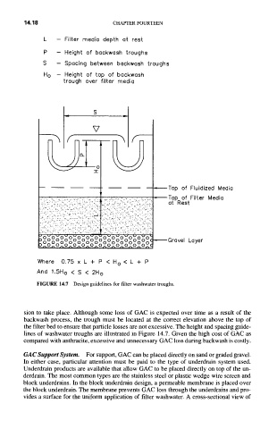
L - Filter media depth at rest
P - Height of backwash troughs
S - Spacing between backwash troughs
H o - Height of top of backwash
trough over filter media
S
V
-L?
~Top of Fluidized Media
• i
"o~b~'o ' o~o~o o "6c'6c'd~'o '00
2~ 0 0 0 0 0 0 ) 0 0 0 0 0
v
)~o..o^o,.o^o~o^,)~o^o^o^o~o,.,I ~ o Go o o ao o o o o lo o o Loyer
o
r
e
Where 0.75 x L + P < H o < L + P
And 1.5Ho < S < 2H o
FIGURE 14.7 Design guidelines for filter washwater troughs.
sion to take place. Although some loss of GAC is expected over time as a result of the
backwash process, the trough must be located at the correct elevation above the top of
the filter bed to ensure that particle losses are not excessive. The height and spacing guide-
lines of washwater troughs are illustrated in Figure 14.7. Given the high cost of GAC as
compared with anthracite, excessive and unnecessary GAC loss during backwash is costly.
GAC Support System. For support, GAC can be placed directly on sand or graded gravel.
In either case, particular attention must be paid to the type of underdrain system used.
Underdrain products are available that allow GAC to be placed directly on top of the un-
derdrain. The most common types are the stainless steel or plastic wedge wire screen and
block underdrains. In the block underdrain design, a permeable membrane is placed over
the block underdrain. The membrane prevents GAC loss through the underdrains and pro-
vides a surface for the uniform application of filter washwater. A cross-sectional view of