Page 187 - 15 Dangerously Mad Projects for the Evil Genius
P. 187

164       15 Dangerously Mad Projects for the Evil Genius


                                                           Step 4. Mount the Transistor
                                                           and Diode

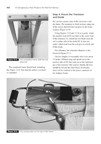
                                                           We can now mount some of the electronics onto
                                                           the frame. The transistor is fixed in place using one
                                                           of the screws that hold the top piece of the frame
                                                           in place (Figure 13-9).
                                                             Using Figures 13-9 and 13-10 as a guide, solder
                                                           the negative lead of D2 (no line) to the center lead
                                                           of the transistor T2. Attach the two leads from the
                                                           coil to either side of the diode D2. It does not
                                                           matter which lead from the coil goes to which side
                                                           of the diode.
                                                             For reference, the schematic diagram is also
                                                           shown in Figure 13-11.
                                                             Cut two lengths of reasonably thick wire about
         Figure 13-8   The completed frame with the coil   12 inches (300mm) long and attach one to the
                       attached                            positive side of D2 (bar) and one to the rightmost
                                                           pin of the transistor (the source). Ideally, the first
           The completed frame should look something       should be red and the other black. Eventually,
        like Figure 13-8. Note that the author is no kind   these will be soldered to the power connector of
        of carpenter!                                      the Arduino board.


         Figure 13-9   The components on the top of the frame
   182   183   184   185   186   187   188   189   190   191   192