
Page 188 - 15 Dangerously Mad Projects for the Evil Genius
P. 188
Chapter 13 ■ Levitation Machine 165
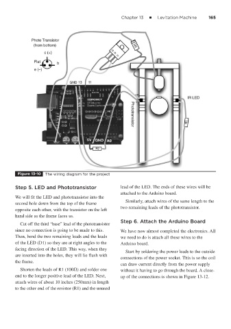
Figure 13-10 The wiring diagram for the project
Step 5. LED and Phototransistor lead of the LED. The ends of these wires will be
attached to the Arduino board.
We will fit the LED and phototransistor into the
Similarly, attach wires of the same length to the
second hole down from the top of the frame
two remaining leads of the phototransistor.
opposite each other, with the transistor on the left
hand side as the frame faces us.
Step 6. Attach the Arduino Board
Cut off the third “base” lead of the phototransistor
since no connection is going to be made to this. We have now almost completed the electronics. All
Then, bend the two remaining leads and the leads we need to do is attach all these wires to the
of the LED (D1) so they are at right angles to the Arduino board.
facing direction of the LED. This way, when they
Start by soldering the power leads to the outside
are inserted into the holes, they will lie flush with
connections of the power socket. This is so the coil
the frame.
can draw current directly from the power supply
Shorten the leads of R1 (100 ) and solder one without it having to go through the board. A close-
end to the longer positive lead of the LED. Next, up of the connections is shown in Figure 13-12.
attach wires of about 10 inches (250mm) in length
to the other end of the resistor (R1) and the unused