Page 189 - 15 Dangerously Mad Projects for the Evil Genius
P. 189

166      15 Dangerously Mad Projects for the Evil Genius


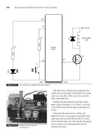
         Figure 13-11  The schematic diagram for the project


                                                             The other wires will all be just poked into the
                                                           sockets that line the edge of the board. If you used
                                                           multi-core wire, this will be easier if you tin the
                                                           wires with solder first.
                                                             Starting with the leads from the LED, attach
                                                           them as shown in Figure 13-10. That is, one lead
                                                           to the GND socket and the other to the Digital 13
                                                           socket.
                                                             Wiring the phototransistor is a little more
                                                           difficult because we are going to attach R2 at the
                                                           same time. Put one end of R2 into the 5V socket
                                                           and fit both the other end of R2 and the lead going
                                                           to the collector of the phototransistor into the
         Figure 13-12  Close-up of the power
                       connections                         Analog In 0 socket.
   184   185   186   187   188   189   190   191   192   193   194