
Page 23 - 15 Dangerously Mad Projects for the Evil Genius
P. 23
4 15 Dangerously Mad Projects for the Evil Genius
indicator LED. The capacitors are all connected in
parallel and charged by the batteries through the
100 resistor when the switch is in the “charge”
position.
The trigger circuit uses a SCR (silicon-
controlled rectifier), or Thyristor as they are
sometimes called. The SCR acts as a conducting
switch when a current passes through its “gate”
connection. This happens when the toggle switch
is put to its “fire” position.
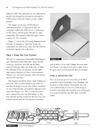
Figure 1-3 shows the full wiring diagram for the
coil gun. To maintain a “gun-like” shape, the
components are laid out in a line, with the batteries
at the back and the coil at the front.
Step 1. Make the Coil Former
The coil is wound onto a disposable ballpoint pen Figure 1-4 Bracket to hold the firing tube
tube. The narrow end of the tube, where the nib
3
would go, should be sawn off and the bung gap of about ⁄8 of an inch (10mm) between them
removed from the other end of the tube. To hold (see Figure 1-6). Epoxy resin glue or glue from a
the windings of the coil in place, we use right- hot glue gun is used to hold the discs in position.
angle plastic brackets cut from a food container
(Figure 1-4). Any kind of plastic with a 90-degree Step 2. Wind the Coil
bend can be used here.
The coil is made up of 13 feet (4m) of 20 AWG
The brackets should be about 1 inch (25mm) on
enameled copper transformer wire. Winding coils
each side. They are then drilled in the center so
by hand is a little tedious. Fortunately, this coil
that they fit snugly over the tube. Drill a small hole
uses a short length of wire. It is worth trying to
on one of the brackets, immediately adjacent to the
wind the coil neatly, but it usually goes off the rails
large hole (Figure 1-5). This is where the inner-
as you get toward the end. This does not really
most connection to the coil will emerge, so the
matter.
hole must be just big enough for the coil wire. The
brackets should then be fixed in place, leaving a
Figure 1-3 The wiring diagram