
Page 27 - 15 Dangerously Mad Projects for the Evil Genius
P. 27
8 15 Dangerously Mad Projects for the Evil Genius
Step 6. The Charging LED
The charging LED will light when the capacitors
are still filling with charge. Once they are full, it
will go off and the gun will be ready for firing. It
is just an LED with a series resistor to limit the
current. It will start bright and gradually get
dimmer as the capacitors get fuller.
Figure 1-13 shows the LED and resistor
soldered across the charging resistor. Note that the
positive (slightly longer) lead of the LED must be
connected to the battery end of the charging
resistor, and the negative end must be connected to
the LED’s current limiting resistor.
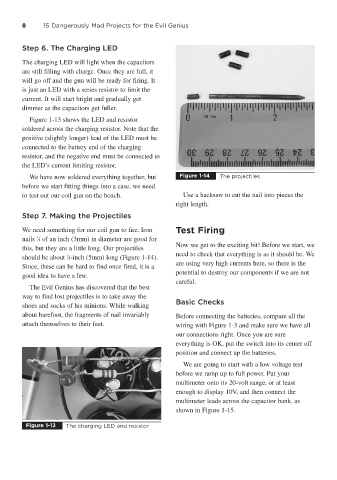
We have now soldered everything together, but Figure 1-14 The projectiles
before we start fitting things into a case, we need
to test out our coil gun on the bench. Use a hacksaw to cut the nail into pieces the
right length.
Step 7. Making the Projectiles
We need something for our coil gun to fire. Iron Test Firing
1
nails ⁄8 of an inch (3mm) in diameter are good for
Now we get to the exciting bit! Before we start, we
this, but they are a little long. Our projectiles
need to check that everything is as it should be. We
should be about ⁄4-inch (5mm) long (Figure 1-14).
1
are using very high currents here, so there is the
Since, these can be hard to find once fired, it is a
potential to destroy our components if we are not
good idea to have a few.
careful.
The Evil Genius has discovered that the best
way to find lost projectiles is to take away the
Basic Checks
shoes and socks of his minions. While walking
about barefoot, the fragments of nail invariably Before connecting the batteries, compare all the
attach themselves to their feet. wiring with Figure 1-3 and make sure we have all
our connections right. Once you are sure
everything is OK, put the switch into its center off
position and connect up the batteries.
We are going to start with a low voltage test
before we ramp up to full power. Put your
multimeter onto its 20-volt range, or at least
enough to display 10V, and then connect the
multimeter leads across the capacitor bank, as
shown in Figure 1-15.
Figure 1-13 The charging LED and resistor