
Page 26 - 15 Dangerously Mad Projects for the Evil Genius
P. 26
Chapter 1 ■ Coil Gun 7
Step 5. Fitting the Batteries
and Switch
The four 9V batteries are connected in series to
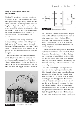
S
1
S1aa a S1b
give a total of 36V. However, fresh batteries may
have upwards of 10V per battery (a total of 40V),
which is above the rated voltage of the capacitors.
To play it safe, the Zener diode in series reduces
this by about 5.6V, bringing the voltage just below
Figure 1-12 Double-throw switch
the capacitors’ rated voltage. Note that exceeding
the rated voltage of electrolytic capacitors is
to R3, which we have already soldered to the gate
dangerous and will shorten the life of the
of the SCR (see Figure 1-3). The other connection
capacitors.
to the trigger throw of the switch should be
Cut the battery leads so they are a more connected to the positive connection of the first
manageable length and then connect the positive battery. For convenience, that can be where the
(red) lead of the first battery lead to the negative battery leads of the first and second batteries are
lead (black) of the second lead, and so on. Finally, soldered together.
connect the Zener diode in series between the last
The switch used has three positions. The center
positive lead and one side of the switch, as shown
position turns both halves of the switch off. This is
in Figure 1-11.
the position shown in Figure 1-12. Push the toggle
The switch is what is called a double-throw one way and the switch will latch on. This will be
switch (Figure 1-12). That is, it is actually two
the charging position. Pulling the toggle lever the
switches operated by a single lever. One of the
other way will connect the switch momentarily, but
“throws” of the switch is used to turn charging on
the switch is sprung to pull the switch back to the
and off, and the other is used as a trigger. We now center off position.
need to connect the “trigger” throw of the switch
So, when connecting the switch you need to
make sure it is the right way around so that the
firing circuit is switched when it goes into its non-
latching action and the charging circuit is made
when the switch is in its latched mode. When the
switch toggle is in the up position, this usually
connects the center connection to the bottom pin,
and vice versa. If you get it wrong the first time,
you will find you have to hold the toggle in the
momentary position to start charging. If this is the
case, just unsolder all the leads to the switch and
flip it through 180 degrees, then solder the leads
up again in the same positions as they were before.
Figure 1-11 The batteries and switch