
Page 24 - 15 Dangerously Mad Projects for the Evil Genius
P. 24
Chapter 1 ■ Coil Gun 5
Figure 1-7 Winding the coil
Figure 1-5 Drilling the bracket
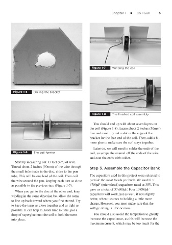
Figure 1-8 The finished coil assembly
You should end up with about seven layers on
the coil (Figure 1-8). Leave about 2 inches (50mm)
free and carefully cut a slot in the edge of the
bracket for the free end of the coil. Then, add a bit
more glue to make sure the coil stays together.
Later on, we will need to solder the ends of the
Figure 1-6 The coil former coil, so scrape the enamel off the ends of the wire
and coat the ends with solder.
Start by measuring out 13 feet (4m) of wire.
Thread about 2 inches (50mm) of the wire through
Step 3. Assemble the Capacitor Bank
the small hole made in the disc, close to the pen
tube. This will be one lead of the coil. Then coil The capacitors used in this project were selected to
the wire around the pen, keeping each turn as close provide the most farads per buck. We used 8
as possible to the previous turn (Figure 1-7). 4700μF (microfarad) capacitors rated at 35V. This
gave us a total of 37,600μF. Four 10,000μF
When you get to the disc at the other end, keep
capacitors will work just as well, if not slightly
winding in the same direction but allow the turns
better, when it comes to holding a little more
to line up back toward where you first started. Try
charge. However, you must make sure that the
to keep the turns as close together and as tight as
voltage rating is 35V or more.
possible. It can help to, from time to time, put a
drop of superglue onto the coil to hold the turns You should also avoid the temptation to greatly
into place. increase the capacitance, as this will increase the
maximum current, which may be too much for the