
Page 25 - 15 Dangerously Mad Projects for the Evil Genius
P. 25
6 15 Dangerously Mad Projects for the Evil Genius
SCR. You may wish to experiment with this, but When both rows of four capacitors are
do understand that when the current becomes too complete, you need to join the common positive
much, it will destroy the SCR. connection of one bank to the common positive of
Figure 1-9 shows how the capacitors are the other bank. Do the same for the negative
connected together into two rows. It is easiest to connections (refer back to the wiring diagram of
make each row of four first and then connect the Figure 1-3).
two rows together.
Step 4. Add the Triggering SCR
Start by lining up four capacitors on their backs
with their legs in the air. Make sure that all the You may be wondering why we need to use a SCR
negative leads are on one side and all the positive and why we couldn’t just use the switch directly
on the other. It’s very important that the capacitors between the capacitors and the coil. The answer is
are connected the right way around. If one of the that no regular switch would withstand the
capacitors is the wrong way around, it could hundreds of amps that flow when the coil is
explode—and capacitors are full of messy goo! triggered. It would simply weld the contacts
Now take some solid core wire and connect all together or melt them.
the negative leads together, and then do the same The SCR that we have chosen is a good
for the positive leads. You can use the same wire as compromise between power handling and price. It
you used to wind the coil, but you will need to will allow peak currents of up to 500A for a
scrape away the insulating enamel where you want millisecond. We are going to need it to handle
to make a solder joint. I used solid core wire of the about 100A for 10 milliseconds.
type employed in domestic electrical wiring. This
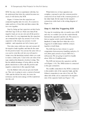
The SCR sits between the capacitors and the
has the added advantage of being able to use the
coil (Figure 1-10). The 100 resistor is connected
plastic insulation to color-code the positive and
to the gate connection.
negative connections to the capacitor bank.
The middle connection to the SCR is connected
Use the thickest wire you can get your hands
to the positive side of the capacitor bank, and the
on. This wire is going to carry a current of around
leftmost connection to one side of the coil. The
100A and the thicker the wire, the lower the
other side of the coil is connected to the negative
resistance and the more energy will be transferred
side of the capacitor bank (see Figure 1-10).
into the coil.
Figure 1-9 Constructing the capacitor bank
Figure 1-10 The SCR and gate resistor