
Page 30 - 15 Dangerously Mad Projects for the Evil Genius
P. 30
Chapter 1 ■ Coil Gun 11
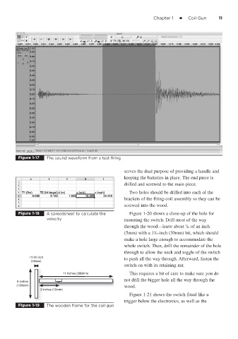
Figure 1-17 The sound waveform from a test firing
serves the dual purpose of providing a handle and
keeping the batteries in place. The end piece is
drilled and screwed to the main piece.
Two holes should be drilled into each of the
brackets of the firing-coil assembly so they can be
screwed into the wood.
Figure 1-18 A spreadsheet to calculate the Figure 1-20 shows a close-up of the hole for
velocity mounting the switch. Drill most of the way
through the wood—leave about ⁄16 of an inch
3
3
(5mm) with a 1 ⁄16-inch (30mm) bit, which should
make a hole large enough to accommodate the
whole switch. Then, drill the remainder of the hole
through to allow the neck and toggle of the switch
11/16 inch to push all the way through. Afterward, fasten the
(18mm)
switch on with its retaining nut.
11 inches (280mm) This requires a bit of care to make sure you do
not drill the bigger hole all the way through the
5 inches
(130mm) wood.
3 inches (75mm)
Figure 1-21 shows the switch fitted like a
trigger below the electronics, as well as the
Figure 1-19 The wooden frame for the coil gun