
Page 59 - 3D Fibre Reinforced Polymer Composites
P. 59
48 30 Fibre Reinforced Polymer Composites
To date the only general manufacturing process that has been used successfully with 3D
fibre preforms is Liquid Moulding (also known as Liquid Composite Moulding). There
are many different variations of Liquid Moulding (LM) and the main techniques will be
reviewed here. However, there are many issues involved in the successful consolidation
of 3D fibre preforms and this chapter can only briefly outline these issues. For a more
detailed explanation the reader is referred to publications such as Kruckenberg and
Paton (1998), Parnas (2000) and Potter (1997).
3.2 LIQUID MOULDING TECHNIQUES
Within the published literature you will find many variations on the theme of liquid
moulding, each with it’s process distinctions that, in the eyes of it’s developers,
differentiate their technique from others and thus make it deserving of its own acronym.
In reality, there are three primary liquid moulding techniques from which the other
processes are derived.
3.2.1 Resin Transfer Moulding
Resin Transfer Moulding (RTM) is the most commonly used of the three main
processes, particularly for the production of high performance aerospace components.
The main aspect of this moulding technique which differentiates it from the following
two processes is the general direction of flow the resin takes as it infiltrates the preform.
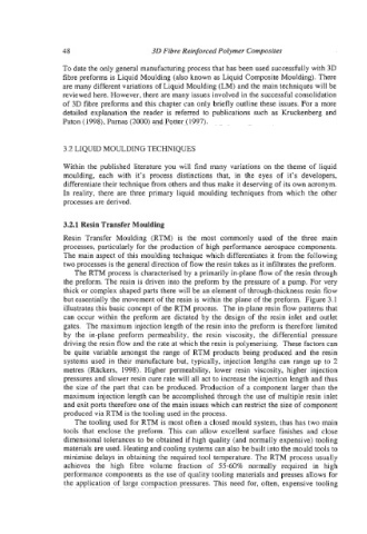
The RTM process is characterised by a primarily in-plane flow of the resin through
the preform. The resin is driven into the preform by the pressure of a pump. For very
thick or complex shaped parts there will be an element of through-thickness resin flow
but essentially the movement of the resin is within the plane of the preform. Figure 3.1
illustrates this basic concept of the RTM process. The in-plane resin flow patterns that
can occur within the preform are dictated by the design of the resin inlet and outlet
gates. The maximum injection length of the resin into the preform is therefore limited
by the in-plane preform permeability, the resin viscosity, the differential pressure
driving the resin flow and the rate at which the resin is polymerising. These factors can
be quite variable amongst the range of RTM products being produced and the resin
systems used in their manufacture but, typically, injection lengths can range up to 2
metres (Rackers, 1998). Higher permeability, lower resin viscosity, higher injection
pressures and slower resin cure rate will all act to increase the injection length and thus
the size of the part that can be produced. Production of a component larger than the
maximum injection length can be accomplished through the use of multiple resin inlet
and exit ports therefore one of the main issues which can restrict the size of component
produced via RTM is the tooling used in the process.
The tooling used for RTM is most often a closed mould system, thus has two main
tools that enclose the preform. This can allow excellent surface finishes and close
dimensional tolerances to be obtained if high quality (and normally expensive) tooling
materials are used. Heating and cooling systems can also be built into the mould tools to
minimise delays in obtaining the required tool temperature. The RTM process usually
achieves the high fibre volume fraction of 55-60% normally required in high
performance components as the use of quality tooling materials and presses allows for
the application of large compaction pressures. This need for, often, expensive tooling