
Page 167 - A Comprehensive Guide to Solar Energy Systems
P. 167
168 A CoMPrehensIVe GuIde To soLAr enerGy sysTeMs
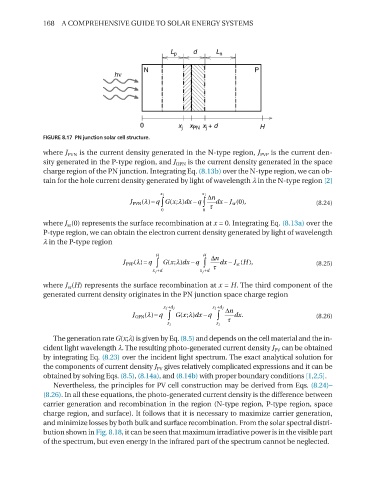
FIGURE 8.17 PN junction solar cell structure.
where J PVn is the current density generated in the n-type region, J PVP is the current den-
sity generated in the P-type region, and J oPn is the current density generated in the space
charge region of the Pn junction. Integrating eq. (8.13b) over the n-type region, we can ob-
tain for the hole current density generated by light of wavelength λ in the n-type region [2]
x j x j ∆n
−
λ = q Gx(;
)
sr
J PVN () ∫ λ dx q ∫ dx − J (0), (8.24)
JPVn(λ)=q∫0xjG(x;λ)dx−q∫0xj∆nτ 0 0 τ
dx−Jsr(0),
where J sr (0) represents the surface recombination at x = 0. Integrating eq. (8.13a) over the
P-type region, we can obtain the electron current density generated by light of wavelength
λ in the P-type region
H H ∆n
−
H
λ = q
)
sr
J PVP () ∫ Gx(; λ dx q ∫ τ dx − J ( ), (8.25)
JPVP(λ)=q∫xj+dHG(x;λ)dx−q∫xj+d x j +d x j +d
H∆nτdx−Jsr(H),
where J sr (H) represents the surface recombination at x = H. The third component of the
generated current density originates in the Pn junction space charge region
x j +d j x j +d j ∆n
−
λ = q
)
J OPN () ∫ Gx(; λ dx q ∫ τ dx. (8.26)
JoPn(λ)=q∫xjxj+djG(x;λ)dx−q∫xjx x j x j
j+dj∆nτdx.
The generation rate G(x;λ) is given by eq. (8.5) and depends on the cell material and the in-
cident light wavelength λ. The resulting photo-generated current density J PV can be obtained
by integrating eq. (8.23) over the incident light spectrum. The exact analytical solution for
the components of current density J PV gives relatively complicated expressions and it can be
obtained by solving eqs. (8.5), (8.14a), and (8.14b) with proper boundary conditions [1,2,5].
nevertheless, the principles for PV cell construction may be derived from eqs. (8.24)–
(8.26). In all these equations, the photo-generated current density is the difference between
carrier generation and recombination in the region (n-type region, P-type region, space
charge region, and surface). It follows that it is necessary to maximize carrier generation,
and minimize losses by both bulk and surface recombination. From the solar spectral distri-
bution shown in Fig. 8.18, it can be seen that maximum irradiative power is in the visible part
of the spectrum, but even energy in the infrared part of the spectrum cannot be neglected.