
Page 162 - A Comprehensive Guide to Solar Energy Systems
P. 162
Chapter 8 • Photovoltaics: The Basics 163
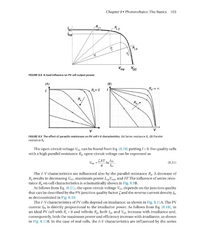
FIGURE 8.8 A load influence on PV cell output power.
FIGURE 8.9 The effect of parasitic resistances on PV cell I–V characteristics. (A) Series resistance R s . (B) Parallel
resistance R p .
The open-circuit voltage V oC can be found from eq. (8.18) putting I = 0. For quality cells
with a high parallel resistance R p , open-circuit voltage can be expressed as
ζ kT
≈ 1 ln I PV . (8.21)
V OC
q I 01 VoC≍ζ 1 kTqlnIPVI01.
The I–V characteristics are influenced also by the parallel resistance R p . A decrease of
R p results in decreasing V oC , maximum power I mp V mp , and FF. The influence of series resis-
tance R p on cell characteristics is schematically shown in Fig. 8.9B.
As follows from eq. (8.21), the open-circuit voltage V oC depends on the junction quality
that can be described by the Pn junction quality factor ζ and the reverse current density J 0 ,
as demonstrated in Fig. 8.10.
The I–V characteristics of PV cells depend on irradiance, as shown in Fig. 8.11A. The PV
current I PV is directly proportional to the irradiative power. As follows from eq. (8.18), in
an ideal PV cell with R s = 0 and infinite R p , both I sC and V oC increase with irradiance and,
consequently, both the maximum power and efficiency increase with irradiance, as shown
in Fig. 8.11B. In the case of real cells, the I–V characteristics are influenced by the series