
Page 202 - A Comprehensive Guide to Solar Energy Systems
P. 202
204 A COmPrehenSIVe GUIDe TO SOlAr enerGy SySTemS
Usually, 2–3 mm thick highly transparent (low iron content) soda lime glass is used
as a cover that provides mechanical rigidity and protection to the module while allowing
light through [2,3,7,15,16]. Usually the glass has an antireflection coating to decrease the
surface reflection [4]. The cell matrix is sandwiched between two layers of the transparent
encapsulated material. The strings are interconnected with auxiliary tabs to form the cell
matrix, which usually consists of several single strings, as shown in Fig. 9.24. Terminals of
the strings are brought outside the module to permit flexible circuit configuration.
Solar cells of very similar parameters (sorted at the end of cell fabrication) are used for
the module assembly. In standard technology, tinned copper ribbons (tabs) are soldered
to the bus bars at the front of the cell to connect the back surface of the adjacent cell, as
shown in Fig. 9.25A and B. The tabs must overlap a long distance along the bus bar length
because the conductance of the printed bus bars is relatively low. Tabs provide a flexible
link between cells that allow thermal expansion mismatch to be accommodated. The as-
sembly is simplified if both cathode and anode contacts are on the rear of the cells (e.g.,
mWT technology), as indicated in Fig. 9.25C.
The outer layer on the nonilluminated module side is usually a composite plastic (ted-
lar) sheet or another glass acting as a barrier against humidity and corrosion that could
accelerate degradation reactions by penetrating the PV module through the surface of the
polymeric backsheet [38] and by diffusing through the encapsulation polymer until they
reach the area between the solar cell and the front glass. Using the glass sheet as the rear
covering layer decreases the degradation rate and increases the module durability (up to
40 years); on the other hand, using glass as the rear covering increases the module weight
and cost.
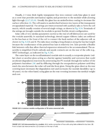
FIGURE 9.24 A common module configuration of 36 series-connected cells.
FIGURE 9.25 Cell interconnection in a module. (A) In series connection of two cells using tabs soldered to bus bars. (B)
Front to back tab interconnection. (C) Contacts on the rear of cells.