
Page 204 - A Comprehensive Guide to Solar Energy Systems
P. 204
206 A COmPrehenSIVe GUIDe TO SOlAr enerGy SySTemS
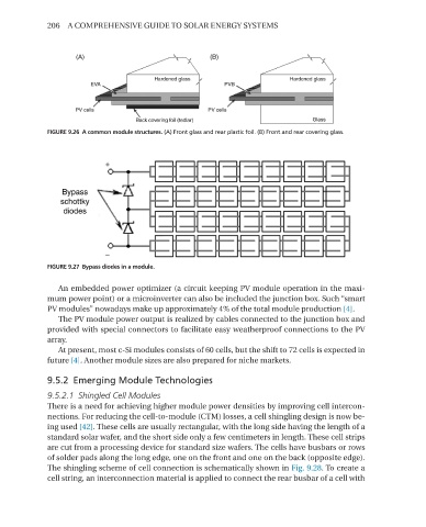
FIGURE 9.26 A common module structures. (A) Front glass and rear plastic foil. (B) Front and rear covering glass.
FIGURE 9.27 Bypass diodes in a module.
An embedded power optimizer (a circuit keeping PV module operation in the maxi-
mum power point) or a microinverter can also be included the junction box. Such “smart
PV modules” nowadays make up approximately 4% of the total module production [4].
The PV module power output is realized by cables connected to the junction box and
provided with special connectors to facilitate easy weatherproof connections to the PV
array.
At present, most c-Si modules consists of 60 cells, but the shift to 72 cells is expected in
future [4]. Another module sizes are also prepared for niche markets.
9.5.2 Emerging Module Technologies
9.5.2.1 Shingled Cell Modules
There is a need for achieving higher module power densities by improving cell intercon-
nections. For reducing the cell-to-module (CTm) losses, a cell shingling design is now be-
ing used [42]. These cells are usually rectangular, with the long side having the length of a
standard solar wafer, and the short side only a few centimeters in length. These cell strips
are cut from a processing device for standard size wafers. The cells have busbars or rows
of solder pads along the long edge, one on the front and one on the back (opposite edge).
The shingling scheme of cell connection is schematically shown in Fig. 9.28. To create a
cell string, an interconnection material is applied to connect the rear busbar of a cell with