
Page 17 - Acquisition and Processing of Marine Seismic Data
P. 17
8 1. INTRODUCTION
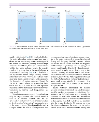
Temperature Salinity Density
M M M
T H P
+ =
Depth Depth Depth
(A) (B) (C)
FIG. 1.5 Physical zones, or clines, within the water column. (A) Thermocline (T), (B) halocline (H), and (C) pycnocline
(P) layers. M represents the surficial, or mixed, water layer.
rapidly with depth (Fig. 1.5B). It is located below pressure create a layer of minimum sound veloc-
the uniformly saline surface water layer and is ity in the water column. It is termed the Sound
characterized by a strong, vertical salinity gradi- Fixing and Ranging (SOFAR) channel, where
ent. Below the halocline, salinity remains high. the sound waves in the seawater are trapped
Below the mixed layer, there is a horizontal layer and travel for long distances without losing their
within the water column where the density energy significantly. The depth where the mini-
gradient is greatest due to the rapid change in mum sound velocity occurs is the axis of the
temperature or salinity (Fig. 1.5C). This layer is channel. Velocity increases above and below
the pycnocline, where a large density contrast the axis because of the temperature and pressure
is therefore observed between the surficial water increases, respectively. Although the location of
layer and deep oceanic waters, which prevents the SOFAR channel axis varies with the temper-
the formation of vertical currents. Except for ature and water depth, it commonly lies
the arctic zones, where no pycnocline layer between 600 and 1200 m below the sea surface
exists, this layer is quite stable and separates in open oceans.
the surficial layer from deep ocean waters where Sound velocity information in marine
variations in salinity and temperature are acoustic applications is vital, especially in some
very small. specific marine geophysical applications. For
Clines in the seawater extend almost horizon- instance, we definitely need sound velocity in
tally for large distances. The vertical stratifica- seawater in sufficient detail for multibeam
tion at a specific location due to the bathymetric surveys to convert the arrival times
temperature and salinity variations as a function of the signals reflected back from the seafloor
of depth creates “channeling” for sound waves into the water depths. In 3D seismic surveys,
in the water column. This channel is located at the distances between the streamers are main-
a depth where the effects of temperature and tained by acoustic communications among the