
Page 316 - Acquisition and Processing of Marine Seismic Data
P. 316
5.9 f-k DIP FILTERS 307
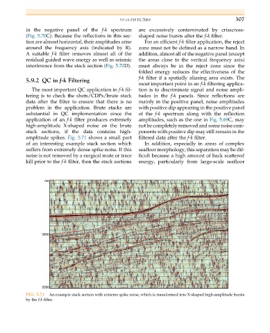
in the negative panel of the f-k spectrum are excessively contaminated by crisscross-
(Fig. 5.70C). Because the reflections in this sec- shaped noise bursts after the f-k filter.
tion are almost horizontal, their amplitudes arise For an efficient f-k filter application, the reject
around the frequency axis (indicated by R). zone must not be defined as a narrow band. In
A suitable f-k filter removes almost all of the addition, almost all of the negative panel (except
residual guided wave energy as well as seismic the areas close to the vertical frequency axis)
interference from the stack section (Fig. 5.70D). must always be in the reject zone since the
folded energy reduces the effectiveness of the
f-k filter if a spatially aliasing area exists. The
5.9.2 QC in f-k Filtering
most important point in an f-k filtering applica-
The most important QC application in f-k fil- tion is to discriminate signal and noise ampli-
tering is to check the shots/CDPs/brute stack tudes in the f-k panels. Since reflections are
data after the filter to ensure that there is no mainly in the positive panel, noise amplitudes
problem in the application. Brute stacks are with positive dip appearing in the positive panel
substantial in QC implementation since the of the f-k spectrum along with the reflection
application of an f-k filter produces extremely amplitudes, such as the one in Fig. 5.69C, may
high-amplitude X-shaped noise on the brute not be completely removed and some noise com-
stack sections, if the data contains high- ponents with positive dip may still remain in the
amplitude spikes. Fig. 5.71 shows a small part filtered data after the f-k filter.
of an interesting example stack section which In addition, especially in areas of complex
suffers from extremely dense spike noise. If this seafloor morphology, this separation may be dif-
noise is not removed by a surgical mute or trace ficult because a high amount of back scattered
kill prior to the f-k filter, then the stack sections energy, particularly from large-scale seafloor
FIG. 5.71 An example stack section with extreme spike noise, which is transformed into X-shaped high-amplitude bursts
by the f-k filter.