
Page 311 - Acquisition and Processing of Marine Seismic Data
P. 311
302 5. PREPROCESSING
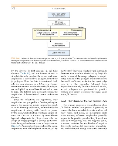
FIG. 5.66 Schematic illustration of the steps involved in f-k filter application. The area containing undesired amplitudes in
the amplitude spectrum is multiplied by a small coefficient in the f-k domain, and then a 2D inverse Fourier transform converts
the filtered data back into the time domain.
by the inverse of that constant in the time the f-k filter, whereas a reject polygon surrounds
domain (Table 4.3), and the inverse of zero is the noise area, which is filtered out by the f-k fil-
simply infinite. In practice, the area of undesired ter. In the case of the accept polygon, the ampli-
amplitudes is selected by a polygon, termed the tudes outside of the polygon are multiplied by
f-k polygon. Then the data is transferred back the small coefficient, while for the reject poly-
into the time domain by a 2D inverse Fourier gon, it is the opposite. Although both
transform after the amplitudes in the f-k polygon approaches normally produce the same results,
are multiplied by a small coefficient value close accept polygons are preferred in practice
to zero. The filtered data does not contain the because it is easier to enclose the signal zone
amplitudes of the undesired events in the time in the f-k domain.
domain.
Since the reflections are hyperbolic, their 5.9.1 f-k Filtering of Marine Seismic Data
amplitudes are grouped in a fan-shaped region
around the frequency axis in the positive panel. The primary purpose of the application of an
In an f-k filtering application, we need only the f-k filter to marine shot gathers is generally to
amplitudes of primary reflections to be passed remove the linear correlated events, such as tail
by the filter, while all other events are simply fil- buoy noise, bird noise, or mechanical cable
tered out. This can be achieved by two different noise. Primary reflection amplitudes generally
types of polygons in the f-k spectrum: either an appear in the positive panel of the f-k spectrum
accept or a reject polygon is defined to discrim- close to the frequency axis. The negative panel,
inate the signal and noise zones in the f-k domain however, contains the amplitudes of negative
(Fig. 5.67). An accept polygon encloses the signal dip events, such as tail buoy noise, aliased sig-
amplitudes that are supposed to be passed by nal, and diffracted energy due to the existence