
Page 307 - Acquisition and Processing of Marine Seismic Data
P. 307
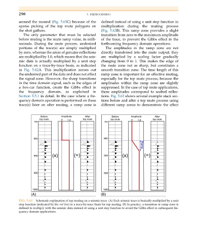
298                                   5. PREPROCESSING

           around the mound (Fig. 5.61C) because of the  defined instead of using a unit step function in
           sparse picking of the top mute polygons on   multiplication during the muting process
           the shot gathers.                            (Fig. 5.62B). This ramp zone provides a slight
              The only parameter that must be selected  transition from zero to the maximum amplitude
           before muting is the mute ramp value, in milli-  of the trace, to prevent the Gibbs effect in the
           seconds. During the mute process, undesired  forthcoming frequency domain operations.
           portions of the trace(s) are simply multiplied  The amplitudes in the ramp zone are not
           by zero, whereas the areas of genuine reflections  directly transferred into the mute output; they
           are multiplied by 1.0, which means that the seis-  are multiplied by a scaling factor gradually
           mic data is actually multiplied by a unit step  changing from 0 to 1. This makes the edge of
           function on a trace-by-trace basis, as indicated  the mute zone not as sharp, but constitutes a
           in Fig. 5.62A. This multiplication zeroes out  smooth transition zone. The time length of this
           the undesired part of the data and does not affect  ramp zone is important for an effective muting,
           the signal zone. However, the sharp transitions  especially for the top mute process, because the
           in the time domain signal, such as the edges of  amplitudes within the ramp zone are slightly
           a box-car function, create the Gibbs effect in  suppressed. In the case of top mute applications,
           the  frequency  domain,   as  explained  in  these amplitudes correspond to seabed reflec-
           Section 5.5.1 in detail. In the case where a fre-  tions. Fig. 5.63 shows several example stack sec-
           quency domain operation is performed on these  tions before and after a top mute process using
           trace(s) later on after muting, a ramp zone is  different ramp zones to demonstrate the effect


           FIG. 5.62  Schematic explanation of top muting on a seismic trace. (A) Each seismic trace is basically multiplied by a unit
           step function (indicated by the red line) in a trace-by-trace basis for top muting. (B) In practice, a transition or ramp zone is
           defined to multiply with the seismic data instead of using a unit step function to avoid the Gibbs effect in subsequent fre-
           quency domain applications.