
Page 312 - Acquisition and Processing of Marine Seismic Data
P. 312
5.9 f-k DIP FILTERS 303
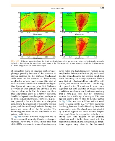
FIG. 5.67 Either an accept (encloses the signal amplitudes) or a reject (encloses the noise amplitudes) polygon can be
defined to discriminate the signal and noise zones in the f-k domain. (A) Accept polygon and (B) its f-k filter output.
(C) Reject polygon and (D) its f-k filter output.
of subsurface faults or irregular seafloor mor- swell noise and high-frequency random noise
phology, possibly because of the existence of amplitudes. Primary reflections (R) are located
canyon systems on the seafloor. Mechanical in a fan-shaped zone in the positive panel close
cable noise can be observed as linear strong to the frequency axis in the f-k spectrum. There is
amplitudes in both panels, since this kind of very distinctive horizontal bird noise (B) in both
noise may occur in the near to far channel (pos- panels, and linear tail buoy noise (T) in the neg-
itive dip), or vice versa (negative dip). Bird noise ative panel in the f-k spectrum. In some cases,
is vertical in shot gathers and effective on the especially for data collected in rough weather
channels close to the bird locations, and thus, conditions, swell noise amplitudes are so strong
their amplitudes arise in a narrow frequency that a band-pass filter may not completely
band in both positive and negative panels paral- remove them. Although a band-pass filter was
lel to the wavenumber axis. Therefore, in prac- applied prior to the f-k filter to the shot gather
tice, generally the amplitudes in a triangular in Fig. 5.68A, the data still has residual swell
area close to the wavenumber axis in the positive noise (S) components in a very low-frequency
panel, and almost all amplitudes in the negative band (e.g., between 0 and 4 Hz) along the whole
panel, are removed in the f-k spectra. The wavenumber axis. The direct wave is indicated
remaining part contains the amplitudes of the by D, which appears as a linear event in the pos-
primary reflections. itive panel. Since its propagation velocity is rel-
Fig. 5.68A shows a marine shot gather and its atively low with respect to the primary
f-k spectrum with some significant events super- reflections, and it is the linear event with the
imposed. Before the f-k filter, a band-pass filter highest inclination on the shot gather, its ampli-
of 8–180 Hz was used to remove low-frequency tudes appear very close to the horizontal