
Page 95 - Acquisition and Processing of Marine Seismic Data
P. 95
86 2. MARINE SEISMIC DATA ACQUISITION
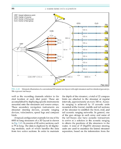
FIG. 2.42 Schematic illustration of a conventional 3D seismic tow layout with eight streamers and two identical gun arrays.
TBs represent tail buoys.
well as the recording channels relative to the the depth of the streamer, a total of 22 compass
shot location at each shot point. These are birds are attached to the streamer at regular
accomplished by deploying specific instruments intervals, approximately at every 300 m. Acous-
mounted onto the streamers and source arrays. tic ranging is achieved by 10 acoustic units
These secondary navigation instruments are mounted at the frontal, middle and tail sections
streamer steering devices, acoustic ranging of the streamer to establish the front, mid, and
devices, velocimeters, speed logs and compass tail acoustic ranging networks. In general, one
birds. of the gun strings in each array and some of
A typical configuration example for one of the the tail buoys also have acoustic transceivers
6000 m-long streamers of a 3D layout is shown to arrive at a solution in the acoustic ranging
in Fig. 2.43. It consists of 80 active sections; each to obtain the positions of the streamers in the
is 75 m long. The data is digitized by 40 digitiz- water. A total of 15 DigiFIN streamer steering
ing modules, each of which handles the data units are used to maintain the lateral streamer
from two active sections. In order to maintain separation, based on the information from the