
Page 96 - Acquisition and Processing of Marine Seismic Data
P. 96
2.3 3D MARINE SEISMIC ACQUISITION 87
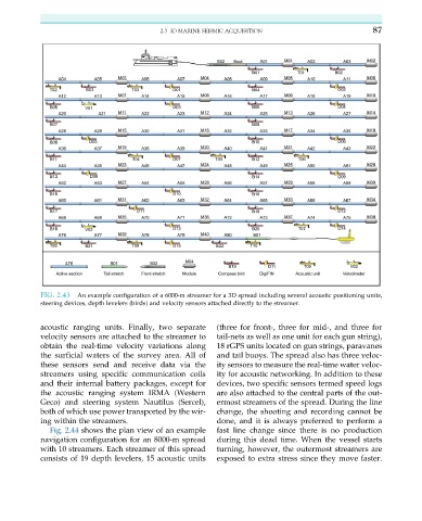
FIG. 2.43 An example configuration of a 6000-m streamer for a 3D spread including several acoustic positioning units,
steering devices, depth levelers (birds) and velocity sensors attached directly to the streamer.
acoustic ranging units. Finally, two separate (three for front-, three for mid-, and three for
velocity sensors are attached to the streamer to tail-nets as well as one unit for each gun string),
obtain the real-time velocity variations along 18 rGPS units located on gun strings, paravanes
the surficial waters of the survey area. All of and tail buoys. The spread also has three veloc-
these sensors send and receive data via the ity sensors to measure the real-time water veloc-
streamers using specific communication coils ity for acoustic networking. In addition to these
and their internal battery packages, except for devices, two specific sensors termed speed logs
the acoustic ranging system IRMA (Western are also attached to the central parts of the out-
Geco) and steering system Nautilus (Sercel), ermost streamers of the spread. During the line
both of which use power transported by the wir- change, the shooting and recording cannot be
ing within the streamers. done, and it is always preferred to perform a
Fig. 2.44 shows the plan view of an example fast line change since there is no production
navigation configuration for an 8000-m spread during this dead time. When the vessel starts
with 10 streamers. Each streamer of this spread turning, however, the outermost streamers are
consists of 19 depth levelers, 15 acoustic units exposed to extra stress since they move faster.