
Page 99 - Acquisition and Processing of Marine Seismic Data
P. 99
90 2. MARINE SEISMIC DATA ACQUISITION
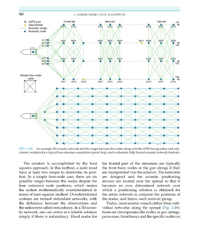
FIG. 2.46 An example 3D acoustic network and the ranges between the nodes along with the rGPS transponders and velo-
cimeter locations for a typical four-streamer acquisition spread (top), and a schematic fully braced acoustic network (bottom).
The solution is accomplished by the least the frontal part of the streamers are typically
squares approach. In this method, a node must the front buoy nodes or the gun strings if they
have at least two ranges to determine its posi- are incorporated into the solution. The networks
tion. In a simple four-node case, there are six are designed and the acoustic positioning
possible ranges between the nodes despite the devices are located over the spread so that it
four unknown node positions, which makes becomes an over determined network over
the system mathematically overdetermined in which a positioning solution is obtained for
terms of least squares method. Overdetermined the entire network to compute the positions of
systems are termed redundant networks, with the nodes, and hence, each receiver group.
the difference between the observations and Today, most seismic vessels utilize three indi-
the unknowns called redundancy. In a 3D acous- vidual networks along the spread (Fig. 2.46):
tic network, one can arrive at a reliable solution front-net (incorporates the nodes at gun strings,
simply if there is redundancy. Fixed nodes for paravanes, front buoys and the specific nodes on