
Page 102 - Acquisition and Processing of Marine Seismic Data
P. 102
2.3 3D MARINE SEISMIC ACQUISITION 93
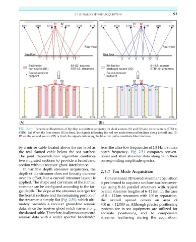
FIG. 2.49 Schematic illustration of flip-flop acquisition geometry for dual sources (S1 and S2) and six streamers (STR1 to
STR6). (A) When the first source (S1) is fired, the signals following the red ray paths form red bin lines along the sail line. (B)
When the second source (S2) is fired, the signals following the blue ray paths constitute blue bin lines.
by a mirror cable located above the sea level as fromtheultra-lowfrequenciesof2.5 Hztosource
the real slanted cable below the sea surface. notch frequency. Fig. 2.51 compares conven-
The joint deconvolution algorithm combines tional and slant streamer data along with their
two migrated sections to provide a broadband corresponding amplitude spectra.
section without receiver ghost interference.
In variable depth streamer acquisition, the 2.3.7 Fan Mode Acquisition
depth of the streamer does not linearly increase
over its offset, but a curved streamer layout is Conventional 3D towed streamer acquisition
applied. The shape and curvature of the slanted is performed to acquire a uniform surface cover-
streamer can be configured according to the tar- age using 8–16 parallel streamers with typical
get depth. The slope of the streamer is larger for overall streamer lengths of 6–12 km. In the case
the frontal sections and the remaining portion of of 8 12 km streamers with 100 m separation,
the streamer is simply flat (Fig. 2.50), which ulti- the overall spread covers an area of
mately provides a receiver ghost-free seismic 700 m 12,000 m. Although precise positioning
data, since the receiver ghost notch varies along systems for in-sea equipment are utilized for
the slanted cable. Therefore, it allows us to record accurate positioning and to compensate
seismic data with a wider spectral bandwidth streamer feathering during the acquisition,