
Page 105 - Acquisition and Processing of Marine Seismic Data
P. 105
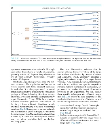
96                            2. MARINE SEISMIC DATA ACQUISITION


           FIG. 2.52  Schematic illustration of fan mode acquisition with eight streamers. The separation between the streamers is
           linearly increased with offset from head to tail for a better coverage for far offsets to minimize the infill time.


           represents a source-receiver azimuth. Although  The term illumination indicates that the
           short offset traces have a variety of azimuths,  energy reflected from everywhere at the target
           generally within  60 degrees, long offset traces  has uniform distribution by means of offsets
           are of poor azimuth distribution, typically  and azimuths, which ultimately provides a
           within  10 degrees.                          high-quality seismic image of the target. In con-
              While 2D acquisition provides only one con-  ventional NAZ surveys, however, target illumi-
           stant azimuth, 3D acquisition enables us to  nation is not uniform and specific acquisition
           record seismic data from different azimuths  patterns, termed multiazimuth acquisition, are
           for each shot. It is always preferred to record  performed to resolve the target illumination
           data rich in azimuth to illuminate the subsurface  problems in 3D exploration. We can classify
           geology in different shooting directions (survey  these specific techniques into different catego-
           azimuths), which can provide a complementary  ries. Fig. 2.55 shows the rose diagrams of azi-
           target illumination (Long, 2009). Incorporating  muth distributions along the offsets for each of
           different azimuths provides visualization of  the following different acquisition patterns:
           the target from different directions, which
                                                        • Narrow-azimuth surveys (NAZ): One single
           ensures a better imaging of all sides of the target
                                                           vessel tows all the streamers and source
           structure. Fig. 2.54 compares a narrow azimuth
                                                           arrays along a single azimuth sail line
           and multiazimuth (three surveys) 3D data from
                                                           (Fig. 2.55A).
           the same survey line. The multiazimuth data has
                                                        • Multiazimuth surveys (MAZ): Several NAZ
           a better S/N ratio and trace-by-trace consis-
           tency, or lateral resolution both for shallow   surveys are performed by one single vessel in
           and deep parts.                                 different sail line azimuths over the same
                                                           target zone (Fig. 2.55B).