
Page 104 - Acquisition and Processing of Marine Seismic Data
P. 104
2.3 3D MARINE SEISMIC ACQUISITION 95
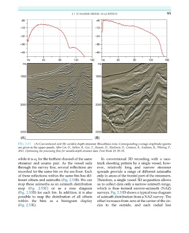
FIG. 2.51 (A) Conventional and (B) variable depth streamer (BroadSeis) data. Corresponding average amplitude spectra
are given in the upper panels. After Lin, D., Sablon, R., Gao, Y., Russier, D., Hardouin, D., Gratacos, B., Soubaras, R., Whiting, P.,
2011. Optimizing the processing flow for variable-depth streamer data. First Break 29, 89–95.
while it is α 2 for the farthest channel of the same In conventional 3D recording with a race-
streamer and source pair. As the vessel sails track shooting pattern by a single vessel, how-
through the survey line, several reflections are ever, relatively long and narrow streamer
recorded for the same bin on the sea floor. Each spreads provide a range of different azimuths
of these reflections within the same bin has dif- only in areas of the frontal part of the streamers.
ferent offsets and azimuths (Fig. 2.53B). We can Therefore, a single vessel 3D acquisition allows
map these azimuths as an azimuth distribution us to collect data only a narrow-azimuth range,
map (Fig. 2.53C) or as a rose diagram which is thus termed narrow-azimuth (NAZ)
(Fig. 2.53D) for each bin. In addition, it is also surveys. Fig. 2.53D shows a typical rose diagram
possible to map the distribution of all offsets of azimuth distribution from a NAZ survey. The
within the bins as a histogram display offset increases from zero at the center of the cir-
(Fig. 2.53E). cles to the outside, and each radial line