
Page 101 - Acquisition and Processing of Marine Seismic Data
P. 101
92 2. MARINE SEISMIC DATA ACQUISITION
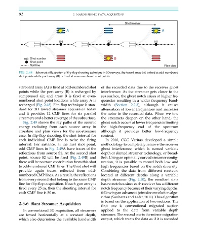
FIG. 2.48 Schematic illustration of flip-flop shooting technique in 3D surveys. Starboard array (A) is fired at odd-numbered
shot points while port array (B) is fired at even-numbered shot points.
starboard array (A) is fired at odd-numbered shot of the recorded data due to the receiver ghost
points while the port array (B) is recharged by interference. As the streamer gets closer to the
compressed air; and array B is fired at even- sea surface, the ghost notch arises at higher fre-
numbered shot point locations while array A is quencies resulting in a wider frequency band-
recharged (Fig. 2.48). Flip-flop technique is stan- width (Section 2.2.3), although it causes
dard for 3D towed streamer acquisition today attenuation of lower frequencies and increases
and it provides 12 CMP lines for six parallel the noise in the recorded data. When we tow
streamers and a better coverage of the subsurface. the streamers deeper, on the other hand, the
Fig. 2.49 shows the ray paths of the seismic ghost notch occurs at lower frequencies limiting
energy radiating from each source array in the high-frequency end of the spectrum
crossline and plan views for the six-streamer although it provides better low-frequency
case. In flip-flop shooting, the shot interval for content.
each individual CMP line is twice the firing In 2010, CGG Veritas developed a simple
interval. For instance, at the first shot point, methodology to completely remove the receiver
odd CMP lines in Fig. 2.49A have traces of the ghost interference, which is named variable
reflections from source S1. At the second shot depth or slanted streamer technology, or Broad-
point, source S2 will be fired (Fig. 2.49B) and Seis. Using an optimally curved streamer config-
there will be no trace contribution from this shot uration, it is possible to record both low and
to odd-numbered CMP lines. The third shot will high frequencies based on the notch diversity:
provide again traces reflected from odd- Combining the data from different receivers
numbered CMP lines. As a result, the reflections located at different depths along a variable
from every second shot belong to the same CMP depth streamer (Fig. 2.50), the resultant data
line for flip-flop acquisition. If each gun array is has no notches since each receiver has a different
fired every 25 m, then the shooting interval for notch frequency because of their varying depths,
each CMP line is 50 m. following an advanced joint deconvolution algo-
rithm (Soubaras and Lafet, 2011). This algorithm
is based on the application of two sections. The
2.3.6 Slant Streamer Acquisition
first one is conventional migrated section
In conventional 3D acquisition, all streamers applied to the data from variable depth
are towed horizontally at a constant depth, streamer. The second one is the mirror migration
which also determines the available bandwidth output, which treats the data as if it is recorded