
Page 218 - Advanced Design Examples of Seismic Retrofit of Structures
P. 218
Example of a Steel Frame Building With Masonry Infill Walls Chapter 4 211
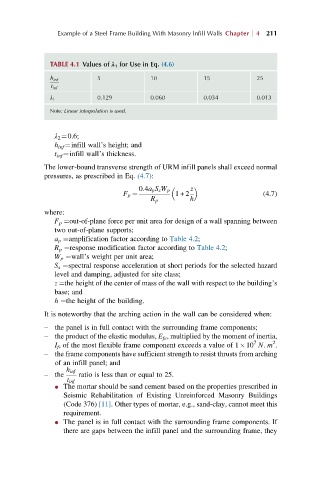
TABLE 4.1 Values of λ 1 for Use in Eq. (4.6)
h inf 5 10 15 25
t inf
0.129 0.060 0.034 0.013
λ 1
Note: Linear interpolation is used.
λ 2 ¼0.6;
h inf ¼infill wall’s height; and
t inf ¼infill wall’s thickness.
The lower-bound transverse strength of URM infill panels shall exceed normal
pressures, as prescribed in Eq. (4.7):
0:4a p S s W p z
F p ¼ 1+ 2 (4.7)
R p h
where:
F p ¼out-of-plane force per unit area for design of a wall spanning between
two out-of-plane supports;
a p ¼amplification factor according to Table 4.2;
R p ¼response modification factor according to Table 4.2;
W p ¼wall’s weight per unit area;
S s ¼spectral response acceleration at short periods for the selected hazard
level and damping, adjusted for site class;
z ¼the height of the center of mass of the wall with respect to the building’s
base; and
h ¼the height of the building.
It is noteworthy that the arching action in the wall can be considered when:
– the panel is in full contact with the surrounding frame components;
– the product of the elastic modulus, E fe , multiplied by the moment of inertia,
7
2
I f , of the most flexible frame component exceeds a value of 1 10 N. m .
– the frame components have sufficient strength to resist thrusts from arching
of an infill panel; and
h inf
– the ratio is less than or equal to 25.
t inf
l The mortar should be sand cement based on the properties prescribed in
Seismic Rehabilitation of Existing Unreinforced Masonry Buildings
(Code 376) [11]. Other types of mortar, e.g., sand-clay, cannot meet this
requirement.
l The panel is in full contact with the surrounding frame components. If
there are gaps between the infill panel and the surrounding frame, they