
Page 219 - Advanced Design Examples of Seismic Retrofit of Structures
P. 219
212 Advanced Design Examples of Seismic Retrofit of Structures
TABLE 4.2 a p and R p Factors
Wall Type a p R p
Connected to the frame at all sides 1.0 1.5
Cantilever and parapet 2.5 2.5
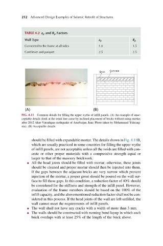
Concrete
Brick
(A) (B)
FIG. 4.11 Common details for filling the upper wythe of infill panels. (A) An example of unac-
ceptable details (look at the weak line cause by inclined placement of bricks without using mortar;
after 2012 Ahar-Varzahgan earthquake of Azerbaijan, Iran; Photo taken by Mohammad Yekrang-
nia). (B) Acceptable details.
should be filled with expandable mortar. The details shown in Fig. 4.11B,
which are usually practiced in some countries for filling the upper wythe
of infill panels, are not acceptable unless all the voids are filled with con-
crete or other proper materials with a compressive strength equal or
larger to that of the masonry brickwork.
l All the head joints should be filled with mortar; otherwise, these joints
should be cleaned and proper mortar should then be injected into them.
If the gaps between the adjacent bricks are very narrow which prevent
injection of the mortar, a proper grout should be poured on the wall sur-
face to fill these gaps. In this condition, a reduction factor of 40% should
be considered for the stiffness and strength of the infill panel. However,
evaluation of the frame members should be based on the 100% of the
infill capacity, and the abovementioned reduction factor shall not be con-
sidered in this process. If the head joints of the wall are left unfilled, the
wall cannot meet the requirements of infill panels.
l The wall shall not have any cracks with a width of more than 3 mm.
l The walls should be constructed with running bond layup in which each
brick overlaps with at least 25% of the length of the brick above.