
Page 221 - Advanced Design Examples of Seismic Retrofit of Structures
P. 221
214 Advanced Design Examples of Seismic Retrofit of Structures
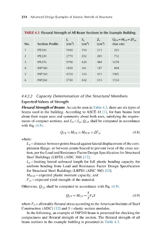
TABLE 4.3 Flexural Strength of All Beam Sections in the Example Building
I x S x Z x Q CE 5M CE 5ZF ye
3
3
4
No. Section Profile (cm ) (cm ) (cm ) (ton cm)
1 IPE200 1940 194 221 583
2 IPE220 2770 252 285 752
3 IPE270 5790 429 484 1278
4 INP180 1450 161 187 494
5 INP240 4250 354 411 1085
6 INP260 5740 442 513 1354
4.4.2.2 Capacity Determination of the Structural Members
Expected-Values of Strength
Flexural Strength of Beams As can be seen in Table 4.3, there are six types of
beams used in the building. According to ASCE 41 [1], for bare beams bent
about their major axes and symmetric about both axes, satisfying the require-
ments of compact sections, and L b <L p , Q CE shall be computed in accordance
with Eq. (4.8).
(4.8)
Q CE ¼ M CE ¼ M PCE ¼ ZF ye
where:
L b ¼distance between points braced against lateral displacement of the com-
pression flange, or between points braced to prevent twist of the cross sec-
tion, per the Load and Resistance Factor Design Specification for Structural
Steel Buildings (LRFD) (AISC 360) [12];
L p ¼limiting lateral unbraced length for full plastic bending capacity for
uniform bending from Load and Resistance Factor Design Specification
for Structural Steel Buildings (LRFD) (AISC 360) [12];
M PCE ¼expected plastic moment capacity; and
F ye ¼expected yield strength of the material.
Otherwise, Q CE shall be computed in accordance with Eq. (4.9).
5
Q CE ¼ M CE ¼ F b S (4.9)
3
where F b ¼allowable flexural stress according to the American Institute of Steel
Construction (AISC) [12] and S¼elastic section modulus.
In the following, an example of INP240 beam is presented for checking the
compactness and flexural strength of the section. The flexural strength of all
beam sections in the example building is presented in Table 4.3.