
Page 49 - Advanced Organic Chemistry Part A - Structure and Mechanisms, 5th ed (2007) - Carey _ Sundberg
P. 49
28 quantity is called the resonance integral and represents the energy of an electron
distributed over two or more overlapping 2p orbitals. For linear polyenes, this equation
z
CHAPTER 1 generates a set of HMOs distributed symmetrically relative to the energy associated
Chemical Bonding with an isolated 2p orbital. The contribution of each atomic orbital to each HMO is
and Molecular Structure z
described by a coefficient:
1/2
2 rj
C = sin (1.16)
rj
n+1 n+1
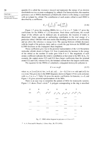
Figure 1.7 gives the resulting HMOs for n = 2to n = 7. Table 1.7 gives the
coefficients for the HMOs of 1,3,5-hexatriene. From these coefficients, the overall
shape of the orbitals can be deduced and, in particular, the location of nodes is
determined. Nodes represent an antibonding contribution to the total energy of a
particular orbital. Orbitals with more nodes than bonding interactions are antibonding
and are above the reference energy level. The spacing between orbitals decreases
with the length of the polyene chain, and as a result, the gap between the HOMO and
LUMO decreases as the conjugated chain lengthens.
These coefficients give rise to the pictorial representation of the 1,3,5-hexatriene
molecular orbitals shown in Figure 1.8. Note in particular the increase in the energy
of the orbital as the number of nodes goes from 0 to 5. The magnitude of each
atomic coefficient indicates the relative contribution at that atom to the MO. In , for
1
example, the central atoms C(3) and C(4) have larger coefficients than the terminal
atoms C(1) and C(6), whereas for the terminal carbons have the largest coefficients.
3
The equation for the HMOs of completely conjugated monocyclic polyenes is
E =
+m (1.17)
j
where m = 2cos 2j /n for j = 0 ±1 ±2 n − 1 /2 for n = odd and (n/2) for
j
n = even. This gives rise to the HMO diagrams shown in Figure 1.9 for cyclic polyenes
with n = 3to n = 7. Table 1.8 gives the atomic coefficients for benzene, n = 6, and
Figure 1.10 gives pictorial representations of the MOs.
There is an easy way to remember the pattern of MOs for monocyclic systems.
Figure 1.11 shows Frost’s circle. 41 A polygon corresponding to the ring is inscribed
2 3 4 5 6 7
. . .
α
Fig. 1.7. HMO orbital diagram for polyenes n = 2to n = 7.
41
A. A. Frost and B. Musulin, J. Chem. Phys., 21, 572 (1953).