
Page 214 - Advances in Biomechanics and Tissue Regeneration
P. 214
(A)
(B)
(C)
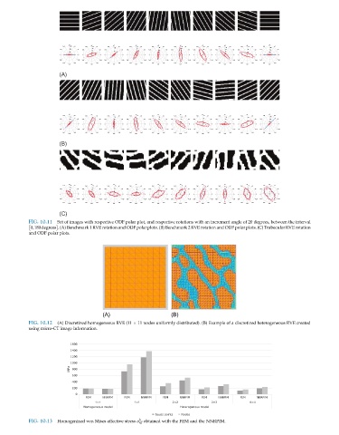
FIG. 10.11 Set of images with respective ODF polar plot, and respective rotations with an increment angle of 20 degrees, between the interval
0,180degrees . (A) Benchmark 1 RVE rotation and ODF polar plots. (B) Benchmark 2 RVE rotation and ODF polar plots. (C) Trabecular RVE rotation
and ODF polar plots.
(A) (B)
FIG. 10.12 (A) Discretized homogeneous RVE (11 11 nodes uniformly distributed). (B) Example of a discretized heterogeneous RVE created
using micro-CT image information.
h
FIG. 10.13 Homogenized von Mises effective stress σ eff obtained with the FEM and the NNRPIM.