
Page 319 - Advances in Biomechanics and Tissue Regeneration
P. 319
16.4 MATHEMATICAL FRAMEWORK 317
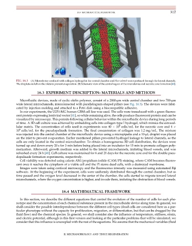
FIG. 16.3 (A) Microdevice confined with collagen hydrogel in the central chamber and blue-colored water perfused through the lateral channels.
The droplets are left on the inlets to prevent evaporation. (B) Schematic view of the central region of the microdevice and necrotic core formation [40].
16.3 EXPERIMENT DESCRIPTION: MATERIALS AND METHODS
Microfluidic devices, made of cyclic olefin polymer, consist of a 2000-μm wide central chamber and two 700-μm
wide lateral microchannels, interconnected with parallelogram-shaped pillars (see Fig. 16.3). The devices were fabri-
cated by injection molding and attached to a Petri dish using a biocompatible adhesive.
In our experiments, the U251-MG human GBM cell line was used. The cells were transduced with a green fluores-
cent protein-expressing lentiviral vector [41], so while remaining alive, the cells produce fluorescent protein and can be
visualized by microscopy. This permits following cellular behavior within the microfluidic device during long periods
of time. A 3D cell culture was achieved by embedding cells into collagen type I hydrogel, which mimics the extracel-
6
lular matrix. The concentration of cells used in experiments was 40 10 cells/mL for the necrotic core and 4
6
10 cells/mL for the pseudopalisade formation. The final concentration of collagen was 1.2 mg/mL. The mixture
was injected into the central chamber of the microfluidic device using a micropipette and a 10-μL droplet was placed
on the inlet to prevent evaporation. Earlier mentioned pillars prevented hydrogel leakage to lateral channels, so the
cells are only located in the central microchamber. To obtain a homogeneous 3D cell distribution, the devices were
turned up and down every 20 s for 3 min before being placed into an incubator for 15 min to promote collagen poly-
merization. Afterward, growth medium was added to the lateral microchannels, imitating blood vessels, and was
refreshed every 24 h [40]. Cell culture was maintained for 6 and 21 days for the necrotic core and for the double pseu-
dopalisade formation experiments, respectively.
Cell viability was detected using calcein AM/propidium iodide (CAM/PI) staining, where CAM becomes fluores-
cent once it reaches the cytoplasm of a viable cell and the PI stains dead cells, with a destroyed membrane.
Images were taken using confocal microscopy and the fluorescence intensity was measured using automated Fiji
software. At the beginning of the experiment, cells were uniformly distributed through the central chamber, but as
time passed and the oxygen level decreased in the center of the chamber, the cells started to migrate toward lateral
microchannels, where the oxygen concentration is higher, and invade them, imitating the obstruction of blood vessels.
16.4 MATHEMATICAL FRAMEWORK
In this section, we describe the different equations that control the evolution of the number of cells for each phe-
notype and the concentration of each chemical substance present in the microfluidic device along time. In general, we
shall consider the possible interdependence between the different cell types (dead cells are considered here as a par-
ticular phenotype without the capacity for proliferation, migration, or differentiation, but that can be dragged by the
fluid flow) and the chemical species. In general, we shall consider also the influence of temperature, stiffness, strain,
and electric potential, although in this first version and looking at the particular problems that will be simulated, we
consider that this influence is uncoupled with the rest of the equations. We assume that the mechanical variables (fluid
II. MECHANOBIOLOGY AND TISSUE REGENERATION