
Page 398 - Advances in Biomechanics and Tissue Regeneration
P. 398
20.2 COMPUTATIONAL MODEL 395
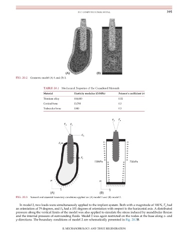
FIG. 20.2 Geometric model (A) 1 and (B) 2.
TABLE 20.1 Mechanical Properties of the Considered Materials
Material Elasticity modulus (E)(MPa) Poisson’s coefficient (ν)
Titanium alloy 110,000 0.32
Cortical bone 13,700 0.3
Trabecular bone 1000 0.3
F b F a
F o F v
F h
F t
F t
730kPa 730kPa
y y
x x
(A) (B)
FIG. 20.3 Natural and essential boundary conditions applied on (A) model 1 and (B) model 2.
In model 2, two loads were simultaneously applied to the implant system. Both with a magnitude of 100N, F a had
an orientation of 79 degrees, and F b had a 101 degrees of orientation with respect to the horizontal axis. A distributed
pressure along the vertical limits of the model was also applied to simulate the stress induced by mandibular flexion
and the internal pressure of surrounding fluids. Model 2 was again restricted on the nodes at the base along x- and
y-directions. The boundary conditions of model 2 are schematically presented in Fig. 20.3B.
II. MECHANOBIOLOGY AND TISSUE REGENERATION