
Page 402 - Advances in Biomechanics and Tissue Regeneration
P. 402
20.4 COMPUTATIONAL ANALYSIS OF BONE REMODELING 399
FIG. 20.5 FEM solution using model 1: final isomaps of (A) apparent density, ρ; (B) von Mises effective stress, σ; and principal stresses (C) σ 11 and
(D) σ 22 .
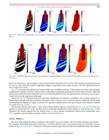
FIG. 20.6 NNRPIM solution using model 1: final isomaps of (A) apparent density, ρ; (B) von Mises effective stress, σ; and principal stresses (C) σ 11
and (D) σ 22 .
below the implant (i.e., apical region), a more intensive bone resorption has occurred. The isomaps of principal stresses
σ 11 and σ 22 show that the model is subjected to higher compression than tensile stresses, since the applied loads are
only compressive loads.
Fig. 20.7A presents the intersection between FEM and NNRPIM solutions. White nodes mean that both methods
predicted the existence of bone, whereas black nodes depict incoherent predictions between both methods. After this
spatial intersection the main trabecular structures of the mandibular bone remained present, confirming a good agree-
ment between both numerical techniques.
Moreover, Fig. 20.7B presents the real trabecular distribution of a baboon’s mandible with a dental implant [23].
These clinical results and the predictions obtained in this work have two common regions: trabecular morphology
surrounding the implant in region A and the low apparent density area in the apical region of the implant marked
by region B in Fig. 20.7B.
The second analysis with model 1, when each load has distinct impacts, is presented in Figs. 20.8 and 20.9. Here, it is
possible to depict that LC1 is the one that leads to trabecular distributions more similar to clinical data (Fig. 20.7B).
Therefore the results suggest that the oblique force, F o , has a greater contribution during bone remodeling, since
LC1 considers a greater impact (greater number of load cycles) for F o .
20.4.2 Model 2
The bone remodeling simulation predicted with model 2 was very similar with the results obtained with model 1.
The isomaps of the final trabecular architecture, von Mises effective stress, and principal stresses of model 2 are pre-
sented in Figs. 20.10 and 20.11. Trabecular distributions predict again bone resorption immediately below the implant
II. MECHANOBIOLOGY AND TISSUE REGENERATION