
Page 418 - Advances in Eco-Fuels for a Sustainable Environment
P. 418
Engine modification for alternative fuels usage in diesel engine 371
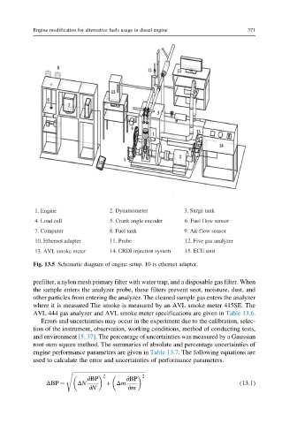
1. Engine 2. Dynamometer 3. Surge tank
4. Load cell 5. Crank angle encoder 6. Fuel flow sensor
7. Computer 8. Fuel tank 9. Air flow sensor
10. Ethernet adapter 11. Probe 12. Five gas analyzer
13. AVL smoke meter 14. CRDI injection system 15. ECU unit
Fig. 13.5 Schematic diagram of engine setup. 10 is ethernet adapter.
prefilter, a nylon mesh primary filter with water trap, and a disposable gas filter. When
the sample enters the analyzer probe, these filters prevent soot, moisture, dust, and
other particles from entering the analyzer. The cleaned sample gas enters the analyzer
where it is measured The smoke is measured by an AVL smoke meter 415SE. The
AVL 444 gas analyzer and AVL smoke meter specifications are given in Table 13.6.
Errors and uncertainties may occur in the experiment due to the calibration, selec-
tion of the instrument, observation, working conditions, method of conducting tests,
and environment [5, 37]. The percentage of uncertainties was measured by a Gaussian
root-sum-square method. The summaries of absolute and percentage uncertainties of
engine performance parameters are given in Table 13.7. The following equations are
used to calculate the error and uncertainties of performance parameters.
s ffiffiffiffiffiffiffiffiffiffiffiffiffiffiffiffiffiffiffiffiffiffiffiffiffiffiffiffiffiffiffiffiffiffiffiffiffiffiffiffiffiffiffiffiffiffiffiffiffiffiffiffiffiffi
2 2
∂BP ∂BP
ΔBP ¼ ΔN + Δm (13.1)
∂N ∂m