
Page 412 - Advances in Renewable Energies and Power Technologies
P. 412
3. Concentrating Solar Power Plants 385
large-scale TES configurations for CSP plants are two-tank direct systems, two-tank
indirect systems, and single-tank thermocline systems. The two-tank direct system
essentially consists of two tanks filled with molten salt, at different temperatures
and fullness levels.
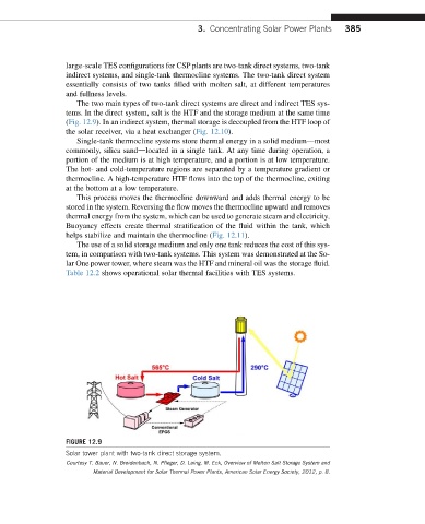
The two main types of two-tank direct systems are direct and indirect TES sys-
tems. In the direct system, salt is the HTF and the storage medium at the same time
(Fig. 12.9). In an indirect system, thermal storage is decoupled from the HTF loop of
the solar receiver, via a heat exchanger (Fig. 12.10).
Single-tank thermocline systems store thermal energy in a solid mediumdmost
commonly, silica sanddlocated in a single tank. At any time during operation, a
portion of the medium is at high temperature, and a portion is at low temperature.
The hot- and cold-temperature regions are separated by a temperature gradient or
thermocline. A high-temperature HTF flows into the top of the thermocline, exiting
at the bottom at a low temperature.
This process moves the thermocline downward and adds thermal energy to be
stored in the system. Reversing the flow moves the thermocline upward and removes
thermal energy from the system, which can be used to generate steam and electricity.
Buoyancy effects create thermal stratification of the fluid within the tank, which
helps stabilize and maintain the thermocline (Fig. 12.11).
The use of a solid storage medium and only one tank reduces the cost of this sys-
tem, in comparison with two-tank systems. This system was demonstrated at the So-
lar One power tower, where steam was the HTF and mineral oil was the storage fluid.
Table 12.2 shows operational solar thermal facilities with TES systems.
FIGURE 12.9
Solar tower plant with two-tank direct storage system.
Courtesy T. Bauer, N. Breidenbach, N. Pfleger, D. Laing, M. Eck, Overview of Molten Salt Storage System and
Material Development for Solar Thermal Power Plants, American Solar Energy Society, 2012, p. 8.