Page 302 - Aerodynamics for Engineering Students
P. 302

284  Aerodynamics for Engineering Students

                    converted to kinetic energy of linear motion. It follows from the definition that this
                    state has zero pressure and zero temperature and thus is not practically attainable.
                      Again applying the energy Eqn (6.17) between reservoir and ultimate conditions


                    so the ultimate, or maximum possible, velocity

                                                                                       (6.27)

                      Expressing the velocity as a  ratio  of  the ultimate velocity and introducing the
                    Mach number:
                                           uz
                                             -
                                           --
                                           C2
                    or


                    and substituting Eqn (6.20a) for T/To:

                                              U          7-1                           (6.28)
                                              C      2+(y-l)M2


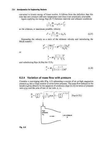
                    6.2.4  Variation of mass flow with pressure
                    Consider a converging tube (Fig. 6.3) exhausting a source of air at high stagnation
                    pressure  po into a large receiver at some lower pressure. The mass flow induced in the
                    nozzle is given directly by the equation of continuity (Eqn (6.22)) in terms of pressure
                    ratio p/po and the area of exit of the tube A, i.e.

                                                              (7-1)l-Y
                               -- k) "'I [ 1 - k)  ]  (Eqn(6.22))
                                            2ypopo
                                 -
                                            7-1


                                                              Low pressure
                                                                  P


                    Fig. 6.3
   297   298   299   300   301   302   303   304   305   306   307