
Page 132 - An Introduction to Microelectromechanical Systems Engineering
P. 132
Sensors and Analysis Systems 111
Excitation AlN
Piezoresistive piezoelectric
torsional shear film
sensor
Silicon fusion
bonding interface Coriolis
force
Axis of
rotation
Direction of
Coriolis oscillation
force
Tuning fork
{100} silicon substrate
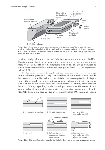
Figure 4.25 Illustration of the angular-rate sensor from Daimler Benz. The structure is a strict
implementation of a tuning fork in silicon. A piezoelectric actuator excites the fork into resonance.
The Coriolis force results in torsional shear stress in the stem, which is measured by a piezoresistive
sense element. (After: [31].)
particular design, all resonant modes of the fork are at frequencies above 10 kHz.
To minimize coupling to higher orders, the primary and secondary modes are sepa-
rated by at least 10 kHz from all other remaining modes. The choice of crystalline
silicon for tine material allows achieving a high quality factor (~ 7,000) at pressures
below 10 −5 bar.
The fabrication process is distinct from that of other yaw-rate sensors in its usage
of SOI substrates (see Figure 4.26). The crystalline silicon over the silicon dioxide
layer defines the tines. The thickness control of the tines is accomplished at the begin-
ning of the process by the precise epitaxial growth of silicon over the SOI substrate.
The thickness of the silicon layer, and consequently of the tine, varies between
20 and 200 µm, depending on the desired performance of the sensor. Litho-
graphy followed by a shallow silicon etch in tetramethyl ammonium hydroxide
(TMAH) define 2-µm-deep cavities in two mirror-image SOI substrates. Silicon
Silicon SiO 2
1. Etch cavity in SOI wafers 2. Silicon fusion bonding 3. Etch front side;
stop on buried oxide
Diffused piezoresistor
Al AlN
4. Etch oxide 5. Define and pattern 6. Back-side etch;
piezoelectric films and stop on buried oxide;
piezoresistors plasma etch release
Figure 4.26 The main fabrication steps for the Daimler Benz micromachined angular-rate sensor.