
Page 133 - An Introduction to Microelectromechanical Systems Engineering
P. 133
112 MEM Structures and Systems in Industrial and Automotive Applications
fusion bonding brings these substrates together such that the cavities are facing each
other. The cavity depth determines the separation between the two tines. An etch step
in TMAH removes the silicon on the front side and stops on the buried silicon diox-
ide layer which is subsequently removed in hydrofluoric acid. The following steps
define the piezoelectric and piezoresistive elements on the silicon surface. Diffused
piezoresistors are formed using ion implantation and diffusion. Piezoelectric alumi-
num nitride is then deposited by sputtering aluminum in a controlled nitrogen and
argon atmosphere. This layer is lithographically patterned and etched in the shape of
the excitation plate over the tine. Aluminum is then sputtered and patterned to form
electrical interconnects and bond pads. Finally, a TMAH etch step from the back side
removes the silicon from underneath the tines. The buried silicon dioxide layer acts as
an etch stop. An anisotropic plasma etch from the front side releases the tines.
The measured frequency of the primary, flexural mode (excitation
mode) was 32.2 kHz, whereas the torsional secondary mode (sense mode) was
245 Hz lower. Typical of tuning forks, the frequencies exhibited a temperature
dependence. For this particular technology, the temperature coefficient of fre-
quency is –0.85 Hz/ºC.
Angular-Rate Sensor from Robert Bosch
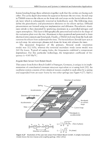
This sensor from Robert Bosch GmbH of Stuttgart, Germany, is unique in its imple-
mentation of a mechanical resonant structure equivalent to a tuning fork [32]. An
oscillator system consists of two identical masses coupled to each other by a spring
and suspended from an outer frame by two other springs (see Figure 4.27). Such a
Direction of oscillation
Spring
Accelerometer
Direction of Coriolis force
Bondpads
Accelerometer to current
loops
Mass
Current loop
Bondpads to
accelerometer
1 k + k 2
1
k 1 k 2 k 2 k 1 f o = 2π (Out of phase)
M M M
1 k 1
Direction of oscillation f = (In phase)
i
2π M
Figure 4.27 Illustration of the yaw-rate sensor from Robert Bosch GmbH. A simple mechanical
model shows the two masses and coupling springs. (After: [32].)