
Page 129 - An Introduction to Microelectromechanical Systems Engineering
P. 129
108 MEM Structures and Systems in Industrial and Automotive Applications
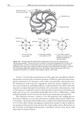
Electrostatic drive
and sense electrodes
Vibrating ring
Anchor
Support flexures
Antinode
Node 45°
Antinode Node
Node Antinode
1. Primary standing 2. Secondary standing 3. Coriolis effect transfers
wave pattern wave pattern at 45° energy to secondary mode
effectively rotating the
vibration pattern
Figure 4.23 Illustration of the Delphi Delco angular-rate sensor and the corresponding
standing-wave pattern. The basic structure consists of a ring shell suspended from an anchor by
support flexures. A total of 32 electrodes (only a few are shown) distributed around the entire
perimeter of the ring excite a primary mode of resonance using electrostatic actuation. A second
set of distributed electrodes capacitively sense the vibration modes. The angular shift of the
standing-wave pattern is a measure of the angular velocity. (After: [29].)
A total of 32 electrodes positioned around the suspended ring shell provide the
electrostatic excitation drive and sense functions. Of this set, eight electrodes strate-
gically positioned at 45º intervals—at the nodes and antinodes—capacitively sense
the deformation of the ring shell. Appropriate electronic circuits complete the sys-
tem control functions, including feedback. A phased-locked loop (PLL) drives the
ring into resonance through the electrostatic drive electrodes and maintains a lock
on the frequency. Feedback is useful to electronically compensate for the mechanical
poles and increase the closed-loop bandwidth of the sensor. Additionally, a high
mechanical quality factor increases the closed-loop system gain and sensitivity.
The fabrication process is similar to the electroplating and molding process
described in Chapter 3, except that the substrate includes preprocessed CMOS con-
trol circuitry. The mold is made of photoresist, and the electroplated nickel ring shell
is 15 to 50 µm thick. Finally, packaging is completed in vacuum in order to minimize
air damping of the resonant ring and provide a large quality factor. Researchers at
the University of Michigan demonstrated a polysilicon version of the sensor with
improved overall performance.